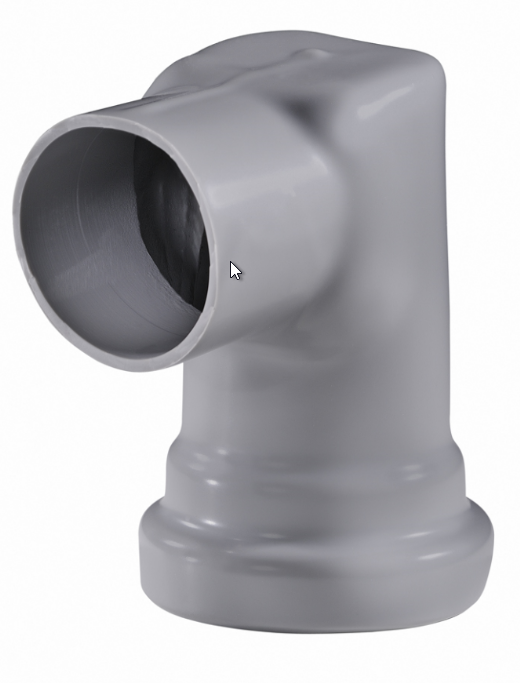
Splash Guards
Product Support and Customer Service
For Further support visit our Contact Page
Safety
Think and act in a safe manner. Always disconnect power and use a lockout before you work on the E-coat system, or any of the related subsystems. Observe any confined space conditions. Use the appropriate safety equipment and clothing for the task. Please carefully read all the instructions listed below to familiarize yourself with the project before attempting to perform any of the work.
Required Materials
- None
Required Tools
- Two (2) 1/2” Wrenches
General
The splash guard serves several functions for open-top TECTRON™ Membrane Electrode (ME) Cells. If spray mist is present, then it serves to keep the inside of the ME Cell clean. If fallen parts are fished out of the paint tank, the Splash Guard keeps paint from going into the ME Cell. If there is not enclosure around the ME Cells, the Splash Guard keeps paint from going into the ME Cell. If there is no enclosure around the ME Cells, the Splash Guard affords some protection against electric shock. It is not designed as a substitute for an e-coat enclosure. If space above the ME Cell is at a minimum, a lower profile version of the Splash Guard is available. (Request P/N 175011)
Step 1
Turn off the supply fluid to the ME Cell by turning off the individual valve. Remove the tubing from the valve/flow indicator.
Step 2
Disconnect the Electrical connection from the ME Cell by:
- if quick-disconnect is supplied, unplug the two connections
- If no quick-disconnect is supplied, use the two wrenches to disconnect the cable lead from the electrode.
Step 3
Slip the Supply Tubing and the Cable Lead (attached at the electrode) through the center of the Splash Guard.
Step 4
Slip Splash Guard onto the Neck of the TECTRON™ ME Cell. Twist the Splash Guard until it faces away from the mist or towards the Supply Manifold if there is no mist. Do not glue the Splash Guard to the Neck of the ME Cell. The friction fit between the two is sufficient to keep the Splash Guard in place.
Step 5
Reattach the Supply Tubing to the Supply Manifold and turn on the fluid. Reconnect the electrical power.
BULLETIN 993107
