TruFlux UF System Manual
Product Support and Customer Service
For Further support visit our Contact Page
Overview
Please read this manual as it relates to your product as this manual covers ALL TruFlux UF Machines. Some items in this manual may or may not apply to the product you have purchased. All end users & installers are strongly encouraged to review this entire manual. Do not take short cuts or skip steps as this will likely lead to a poor installation and poor customer acceptance. Insure that all components (i.e. Valves, gaskets, o-rings, etc) used to complete the installation of this UF Machine are ‘silicone-free’.
Keys to Success:
Make sure there has been no damage during the shipment. Make sure that the horizontal manifolds have not slipped, or fallen down and they are parallel to the ground. Make sure that the piping into and out of the UF Modules are horizontal and square with respect to each other. Attach the items that have been shipped loose except the UF Elements, flush out the piping to remove dust and dirt form shipment and construction, perform a leak check with DI water at 60 psi to make sure that all joints are tight and working properly. Send a sample of the flush water to your E-coat paint supplier and check for contaminates. Once the rinse water sample has been approved, you can connect the UF machine to the E-coat paint piping and get ready to commission the unit. Install the UF Elements, use the CIP system to gently flush each one (one at a time) with buffered DI water (to the same pH as the E-coat paint). Repeat the gentle flush for each Element a second time. This will remove any preservatives from the UF Element as well as gently remove trapped air from inside the UF Element. When you are ready to start the UF Machine gently (take 60 full seconds to slowly open the supply butterfly valve, the outlet valve should be already open). DO NOT OPEN THE VALVE QUICKLY AS THIS WILL DAMAGE THE UF ELEMENTS. After about 3 or 4 hours of operation, record the permeate flow rate for each Module and this will be defined as the Base Line valve. Flush each UF Module at least once a month with permeate for 10 or 15 minutes using the CIP pump. Rest the UF module over the weekend and then bring it back on line the following Monday. The purpose of permeate flushing is to delay the need for chemical cleaning. Never close off both permeate isolation valves unless the inlet & outlet to the UF Module are also closed (these are to be closed first). If the inlet and outlet is open (for normal or CIP operation) and you close off both of the permeate isolation valves you will damage the UF Element.
You should have received the following items: (please contact our Customer Service if you have questions at 219.464.2027 Ext. 28)
- One or more crates containing UF Machine.
- One or more crates containing loose items.
- TruFlux UF Getting Started Guide (this manual) (CD & Hard Copy).
- TruFlux UF System Operator Checklist. (in a 1” notebook binder)
- UF System Flow Schematic
- Installation Video (DVD, VHS or Windows Media File)
General Information
Ultrafiltration (UF) is a pressure driven process for separating and concentrating suspended solids and high molecular weight materials from water and low molecular weight solutes. The heart of the system is a molecular selective, semi-permeable UF membrane. Unlike conventional filtration, the feed stream flows across the UF membrane surface, not perpendicular to it as in cartridge or bag filtration. Additionally, the UF membrane typically does not become plugged because the retained material cannot enter the UF membrane pores. Over time, the membrane becomes coated with paint solids and permeate flow will decrease. The material to be processed is called the feed, material rejected by the UF membrane is called the concentrate, and the material passing through the UF membrane is referred to as the permeate, or flux. The permeate rate is usually expressed in gallons per minute when discussing a specific module or system. When referring to a particular UF membrane in its relationship to a specific process, the terminology most frequently used is gfd or gallons per square foot of membrane per day. The use of gfd measurements allows small laboratory module with a known area to be used for pilot testing and then scaled up to production size equipment. Example: Using a laboratory UF module with 0.186 sm (2 SF) of UF membrane surface area testing a sample liquid produces a permeate rate of 0.003785 cubic meters/hour (1 gallon/hour). Therefore: Metric: 0.003785 cm/hr x 24 hrs/day= 0.0908 cm/day 0.0908 cm/day / 0.186 sm UF membrane surface area = 0.488 cm/sm day English: 1 g/hr x 24 hr/day= 24 g/day 24 gpd / 2 SF UF membrane surface area = 12 gal/SF day If a full scale production unit would require a permeate rate of 2.271 cm/hr (10 gpm) based on a 16 hour work day, the system would require: Metric: 2.271 cm/hr x 16 hrs = 36.336 cm/day 36.336 cm/day / 0.488 cm/sm day = 74.459 sm of UF membrane surface area. English: 10 gpm x 60min/hr. = 600 gal/hr x 16 hr/day = 9,600 gal/day 9,600 gpd / 12 gfd = 800 sq. ft. of membrane area. A typical 8" diameter (nominal is 7.6 inches) x 40" long UF Element will contain approximately 25.5 sm (275 SF) of active membrane surface area. Therefore, in the example above, the system would require a minimum of (3) x 8" UF Elements. 74.459 sm (800 SF) / 25.5 sm/UF Element (275 SF/UF Element) = 2.91, or Round up to 3 UF Elements.
Description of Components
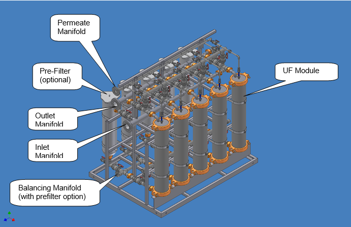
There are two basic types of TruFlux UF Systems. The first is the Single-sided System with UF Modules on one side of the UF Rack and a Double-side UF System with UF Modules on both sides for end-users with higher UF permeate demands. Options include : paint pre-filters (BF) vessels, Clean-In-Place (CIP), total cleaning (TC), and others too.
Maintain Proper Flow Velocity
It is absolutely necessary to design the E-coat paint feed piping to insure that the velocity of the E-coat paint is always about 2.5 to 3.7 meters/second (about 8 to 12 feet/second) The size of the manifold is sized according to the number of UF Modules. In a case where required flow rate calculation falls in between 2 different pipe sizes, the smaller (i.e. faster velocity) will always be selected as long as the piping run is not too long.
TruFlux UF Module Information
The TruFlux UF Module assembly includes the following components:
UF Element
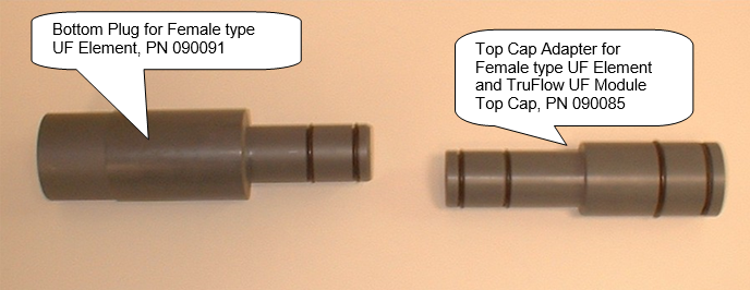
The TruFlux UF System will accept any industrial standard 7640 type UF element. The nominal paint flow per UF element is 265 lpm (70 gpm) and inlet/outlet connection is 1-1/2” Pipe. The UF membrane is wound up on the permeate pipe and is generally referred to as a spiral wound design. The industry standard UF Module is generally about 1015 mm (40 in) long with an extended capped permeate pipe at the bottom end, or a removable plug. The upper end of the permeate pipe makes the connection to the Top Cap of the UF Housing. The upper end can either be a so-called male design with two O-rings or a female type where the ID of the permeate pipe has been bored out. If the UF Element has a female permeate connections then adapters (UFS PN 090091 & 090085) are necessary to make the connection to the Bottom and Top Cap (respectively) of the UF Housing. One or more ends of the UF Element have an anti-telescoping device (ATD) and a hard fiberglass outer wrap. The paint outlet end has either one or two E-coat paint seals. Sometimes these E-coat paint seals are called U-cup, Lip seals, square cut, etc. If two paint seals are furnished, the seals should be installed "back-to-back" with the open ends facing away from each other. If one seal is furnished, it should be installed with the open end down (facing the flow of the E-coat paint so that the prevailing flow will expand the seal outward into the housing body). In any event these E-coat paint seals must be installed at the top of the UF Element. If they are installed on the bottom then E-coat paint solids can fill in above this seal and make the removal of the UF Element very difficult, if not impossible.
TruFlow UF Housing with 304L Stainless Steel End (Top & Bottom) Caps
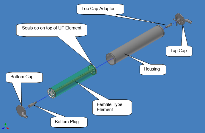
The UF Housing is manufactured from Schedule 80 PVC or 11 ga 304 SS with an 8" groove type coupling groove at both ends. In the center of the Top Cap on the underneath side is a coupling adapter that slips over the "O" rings on the male permeate pipe, or the male adapter (if a female type UF Element is being used, then Order UFS PN 090085 [1 required per UF Module] which will connect the female permeate connection of the UF Element to the female connection on the bottom side of the Top Cap.). If the UF Element has a female connection on the other end to, then use the Bottom Adapter Plug (UFS PN 090091).
The E-coat paint inlet and outlet connections are made through the bottom and top end Caps. The permeate discharge connection on the top side of the Top Cap is a 3/4” NPT female thread (i.e. full coupling), which can be attached to a flow meter. The E-coat paint inlet to the UF Housing must be at the bottom and the outlet is at the top.
Permeate Flow Meters
Each TruFlow UF Module has an individual flow meter with a range of 3.8 – 37.8 lpm (1.0 – 10.0 gpm). Do not use a tool to tighten or remove these fragile flow meters. Only use your hand to tighten and loosen.
TruFluxTM UF Systems Options
TruVelocity UF Paint 304 Stainless Steel Manifolds
The diameter of the manifolds vary as the E-coat paint is delivered to the UF Modules so that the velocity of the E-coat paint in the manifolds stays nearly constant in the proper range. In this fashion, the velocity of the E-coat paint is properly maintained to reduce the opportunity for E-coat paint solids to settle out of solution and to keep the piping system free of paint solids blockages. The end of the TruVelocity UF Manifold which is largest is called the major diameter. The major diameter also has a flange connection as well as a butterfly valve of the same size as the major diameter. The discharge piping of the UF feed pump is usually attached to the lower manifold. The TruVelocity manifold includes an integral E-coat paint bypass valve (BPV). This bypass connects the termination end of the E-coat paint feed manifold to the E-coat paint return manifold. The BPV needs to be cracked open so that some paint is allowed to circulate through this by pass to avoid E-coat paint build up at the terminations of the E-coat paint manifolds.
Bag Filter Vessels
Important Note – you must always specify Bag Filters bags that are glazed or heat treated to eliminate lint. Use bag material that is approved by your paint supplier. Use UFS PN 205028, or equal. The E-coat paint must be prefiltered before it enters the UF Modules. The spiral wound UF Element has narrow passage ways that can be blocked by dirt bits and other large particles. Use a 25 micron rated bag (maximum) that is approved by your E-coat paint supplier. Use at least 2 separate filter vessels (i.e. duplex) so that E-coat paint flow is ALWAYS going to the UF System and change only one filter vessel at a time. If just one prefilter vessel is used, the longevity of the UF Modules will be reduced even if paint flow is stopped for 10 seconds or so. Plan on only 22.7 cubic m/hr (100 gpm) or less per Bag Filter vessel.
UF Supply Pump
Double Mechanical Seal with Seal Flush is always required on horizontal pumps which pump paint or permeate.
E-coat Paint Flow Meter
Proper knowledge of the actual E-coat Paint flow is important in troubleshooting UF performance. UFS Corporation offers the TigerMag EP flow meter contact UFS Corporation for more information on this option. Click here to see more information Sparling Instruments.
Clean In Place (CIP)
CIP cleaning system consists of a cleaning tank, circulation pump capable of cleaning one UF Element at time, 5 Hp 460 V AC 3 ph 60 Hz motor control station for the CIP system, cooling heat exchanger, and dual temperature controller. Motor disconnect is not included.
Total System Cleaning
Total System Cleaning requires an additional pump rated with the same rating as the paint supply pump so all the UF modules can be cleaned at one time. The holding tank also needs to be enlarged according to the number of UF Modules in operation.
Permeate Storage Tank
Permeate is used to rinse off excess paint from the parts. The storage tank can be sized for your application. The permeate supply pump is also required to supply fresh permeate to the rinse system. Contact UFS Corporation for more information.
Turbidity Sensor
Turbidity is the measure of how clear the fluid is. Generally, permeate has a very low turbidity reading which means that it’s very clear. If there is a leak in one of the UF modules, then the turbidity will be a higher value and it will be more opaque. Contact UFS Corporation for more information on this sensor. Turbidity sensor must be placed properly to avoid false alarms from air bubbles.
Permeate Flow Monitor System
UFS Corporation offers a permeate flow monitoring system that provides remote monitoring of the permeate flow from each individual UF module. This system can be integrated with your PLC system to provide trend charts, alarms, and reports. Contact UFS Corporation for more information.
Stainless Steel UF Housing
If you do not want a PVC housing then you can order one made from 12 Ga 304 Stainless Steel.
UF Flow Schematic (Drawing 997303)
The flow of E-coat paint through the UF System typically begins as E-coat paint is drawn from the E-coat tank by a UF Paint Feed pump. Next it is pre-filtered to 25 microns, or less, with a glazed or heat fused bag filter. The E-coat paint enters the UF System and is allowed to pass by the face of the UF membrane inside the UF Modules. Permeate solution contains low molecular weight material such as water, ions, and salts which pass through the UF membrane. All the larger particles such as the E-coat paint solids are rejected by the UF Membrane. These are then returned to the E-coat paint tank. These are general instructions that can be applied to any TruFlux UF Machine. In some cases, your UF Machine may not have all the options and some steps refer to a valve ID that will not be included with your machine. If this is the case, please move to the next step. See TruFlux Ultrafiltration Machine Piping Schematic at the end of this document for Valve Locations. For extra copies ask for UFS Part Number 997303. Permeate solution is used to either rinse off the excess E-coat paint off the painted parts or else is purged to maintain paint bath chemistry. Please see the Truflux UF Machine Flow Schematic Drawing in the appendix.
Minimum System Requirements
The UF system requires the following components in order to function properly: UF paint feed pump, duplex paint Bag Filter vessels, glazed or heat treated 25μ polyethylene Bag filter bags, 2 or more UF Modules, permeate storage & circulation pump(s), and UF Module cleaning system. If these were not included in your order, they will have to be purchased by the end-user or the installation contractor.
TruFlux UF System Requirements by Others
Paint, Permeate, and Clean Drains
A suitable drain is required for paint (back to the E-coat bath), permeate (either back to the E-coat bath or waste), and cleaning solution (back to waste).
Electrical Needs for CIP
The CIP System requires 460 (+/- 10%) V AC 3 ph 60 Hz power for the: 5 hp pump motor, cooling water solenoid valve (6 watts), and dual set point temperature controller (12 watts). Internal transformer supplies 120 V AC to the temperature controller, motor starter coil, panel lights, etc.
E-coat Paint Supply
ALWAYS SOFT START E-coat PAINT PUMP TO AVOID HYDROLIC SHOCK TO UF ELEMETS. All UF Feed Pumps must be equipped with a soft start controller. The controller shall be adjustable so that the motor does NOT reach full speed until 20-30 seconds after startup. Each 8” UF Module requires a minimum of ~16 cubic meter/hr (70 gpm) of E-coat paint at 4 – 4.5 Bar (55 psi – 65 psi) pressure at the inlet E-coat paint manifold of the TruFlux UF system.
Duplex E-coat Paint Prefilters
If the TruFlux UF System does not include Bag Filter Vessels, then customer must supply a duplex Bag Filter system that filters the E-coat paint to 25 microns, maximum. Use only glazed or heat treated bag filters. Polyethylene or polypropylene bag filters are generally acceptable to most E-coat paint supplier. Check with them to confirm.
Clean Solution RO Water or DI Water Make-up
The customer must provide the appropriate piping and valves to fill the CIP tank with RO water (or DI water). Generally a 1” line is sufficient.
Close Proximity above the Rim of the E-coat tank
The TruFlux UF System needs to be placed near the UF Feed pump and no more than 1 -1.5m (3 - 5 ft) above the discharge of the UF feed pump. If the location is any higher above the rim of the E-coat tank, then the pump pressure discharge rating will have to be increased to compensate for the height of the UF System above the discharge of the UF Feed pump. If the UF System has to be placed on the same grade as the E-coat tank. Some special equipment will be needed to return E-coat paint back to the E-coat tank when a Bag Filter is changed, UF Element is replaced, etc. Usually low pressure air can be connected to the top of the Bag Filter vessel and the paint can be blown back to the E-Coat tank. If you do not first isolate the Bag Filter Vessel and allow air into the UF Element you can damage the UF Element. The air used to blow down the Bag Filters must be oil free and clean of dirt. Also take care not to create foam due to the air entering the E-coat tank.
System Information
Single Pass Design
The TruFlux UF machine is designed using the "single pass" process. In this design, the paint is pumped into the UF Modules and returns directly to the paint tank. Each UF Module consists of: an UF plus a UF Housing. For the purposes of estimating permeate production UFS Corporation suggests using 0.5 cubic m/hr (2.25 gpm) of permeate per 8” UF Module even though it may produce more at start up.
Estimating Permeate Requirement
A typical 8” UF Element can produce as much as 0.7 – 0.9 cubic m/hr (3 - 4 gpm), or even more in some cases, just after startup, but this rate is not reliable for the long term. The steady state permeate rate for an 8’-inch UF Element is 0.56 cm/hr (2.5 gpm) +/- 10%. UFS recommends that you be conservative and only expect to get 0.5 cubic m/hr (2.25 gpm) per 8” UF Module. Generally, the amount of permeate required is a function of the Painted Through Put (PTP) that is processed by the E-coat Paint System. The typical UF permeate criteria is to have 1.83 lpm/sm/min (4.5 gpm per 100 SF/min) of work. Your paint supplier should recommend a permeate flow rate for your system.
Monorail Systems
This is calculated by taking the JPH (jobs per hour) times the surface area/job divided by 60 min/hour. For example: if the jobs per hour are 100 and the surface area per job is 50 sm, the PTP is 100 jph x 50 sm/job / 60 min/hr = 83.3 sm/minute (896.6 SF/min). Then the permeate requirement is Metric: 83.3 sm/min x 1.83 lpm/sm = 152 lpm English 896.6 SF/min x 4.5 gpm / 100 SF/min = 40.3 gpm
- of 8” UF Elements recommended = 40.3 gpm / 2.25 gpm/8” UF Element = 17.9 or Round up to 18 x 8” UF Elements.
Hoist Systems
Important Note: The E-coat system is only painting when the parts racks are in their full down position and power is on. Calculate the work design rate (JPH) by dividing 60 minutes by the ‘Power-On’ time. For example, if your total cycle time is 5 minutes (or 12 racks painted per hour), but the ‘Power On’ time is only 3 minutes (i.e. it takes two more minutes to hoist the rack, index and lower in the next rack). The PTP = 60 min/hr / 3 min/job = 20 ‘Work Design Rate’ JPH. If the surface area is say 15 sm (161.5 SF), then the PTP is 20 WDR jph x 15 sm/job / 60 min/hr = 5 sm/min (53.9 SF/min). If you use the actual 12 JPH you will undersize the UF System. The rinsing must occur during the same 3 minutes that the power in on. Then the permeate requirement is Metric: 5 sm/min x 1.83 lpm/sm = 9.15 lpm English 53.9 SF/min x 4.5 gpm / 100 SF/min = 2.426 gpm
- of 8” UF Elements recommended = 2.426 gpm / 2.25 gpm/8” UF Element = 1.1 or Round up to 2 x 8” UF Elements. UFS Does not recommend using just one 8” UF Element because there is not fault tolerance, so the minimum number of UF Elements is 2.
Setup & Making Connections
Read the entire section first before proceeding. The System must be set in place, components need to be verified they are in the correct position and then a leak check must be done before any E-coat paint connections are made.
Groove Clamps
Groove clamps are used in making connections where as in the past a threaded connection or flange might have been used. The typical groove clamp used in the TruFlux UF System are ‘Lightweight’ 7000 style from Anvil International (Gruvlock brand), which are typically used up to 41.4 Bar (600 psi). If you have trouble finding these then the following substitution can be made: Victaulic Style 75; or Anvil Corporation maker of Gruvlock brand Anvil, or Central Grooved Pipe Products Central Sprinkler Figure 705. The groove clamp gasket material is EPDM. If you purchase a gasket locally make sure it does not have any silicone lubricant. You must tighten the nuts alternately and equally. Do not tighten one nut completely then tighten the other one completely – this can result in a leak or damage to the equipment. You can use hand soap (if approved by your paint company) or glycerin to lubricate the groove clamp gaskets. Make sure the gasket is centered over the joint before trying to place the groove clamp in place.
Required Tools & materials
The following tools will be required to install the TruFlux UF System
- 1-1/4” or 11/16” socket to tighten 8” groove clamps
- Torque wrench
- 11/16” deep well socket to tighten 2” and 1-1/2” groove clamps
- 7/8” deep well socket to tighten 3” groove clamps
- 15/16” socket for 5/8” bolt hardware on 4” flange
- 15/16” Open end wrench for 5/8” bolt hardware on 4” flange
- ¾” Open end wrench to tighten hardware on E-coat paint manifold cantilever supports
- Flat blade screw driver & pliers to tighten 2 piece pipe clamps
- Large scissors to cut nylon tie wraps
- ~30 cm (12”) long bubble level6 x large jaw metal C Clamps
- Electric Drill with 12.7 mm (½”) concrete drill bit
- 1 m (3’ or 4’) long bubble level
- 9/16” socket for lag screws that connect
The following materials will be required to install the TruFlux UF System
- 12 x 1 mm steel shims [3 cm x 2 cm]
- 12 x 2 mm steel shims [3 cm x 2 cm]
- 12 x 3 mm steel shims [3 cm x 2 cm]
- 12 x 12.7 mm (½”) OD by 10.1 cm (4”) long concrete floor [wedge] anchors
- In addition there will be piping, electrical wiring & hardware, and other items as required to complete the installation.
The following tools are optional
- Electric impact wrench
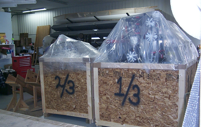
Typical Crate Identification
The TruFlux UF system will be typically be shipped in two or more crates. Please use the following pictures to identify what is in each of the crates. The UF rack and CIP will be shipped in one or more crates based upon the overall length of the skid and any special customer requirements for handling at the job site.
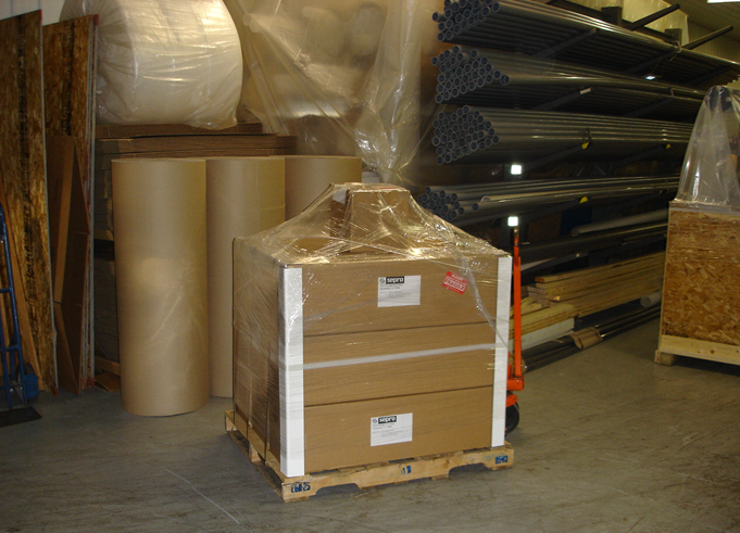
The UF elements are always shipped loose and are typically in cardboard boxes. These boxes are placed on a wood skid and the shrink wrapped.
Long PVC piping elements that are shipped loose are either secured to horizontal supports in the UF rack, placed inside another wooden crate (for example that might contain Membrane Electrode Cells, if this product was also ordered.), or placed on a separate wood skid.
Look for shipping damage
Take a careful look at the sides of each crate or shipping skid and look for damage caused by a fork truck or rough handling during shipment. Report this damage to your carrier immediately.
Uncrating & Placement
Carefully move the crates and shipping skids as close to the final resting place as possible. Begin to take the wood crates by removing the plywood skirt that surrounds the lower portion of the assembly. Next you can remove the plastic sheeting that covered the upper portion of the assembly. Use a scissors to cut the beige, clear or white colored nylon tie wraps. Take care not to cut anything else when performing this step. Set aside any PVC piping that may be have been attached to protect it during shipment in a clean safe environment. Use a 9/16” socket to remove the lag screws that secure the metal skids to the 4” x 4” wood skids. Note there is a rubber isolator between the mounting point on the skid and the wood skid. Throw these away as the UF machine is not meant to be mounted on rubber isolators. Do not remove any protective tape covering the of pipe opening until the opening is too used in order to keep dust and dirt from entering the piping. Take care when removing any protective tape to not lose any O-ring that is located in the gland cavity.
Match marks
Match marks were used to identify to pieces that need to be reassembled. These are typically black letters or numbers printed on a yellow label.

Two pieces with the same match mark should be brought together.
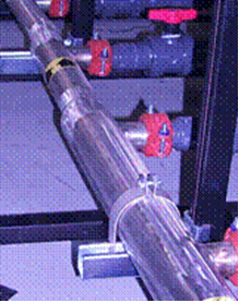
Groove Clamp Gaskets Must be already in place
Groove clamps require a gasket to cover the pipe joint. It is important to make sure the appropriate gasket is already in place before two skids or pipe sections are moved together. If you do not place the gasket in first you will have to move the skids apart in order to place the gasket in its proper location.

Pointer shows groove clamp gasket in place.
Placement of Skids to form UF Machine
If your UF machine was large enough are required that it be split into for shipment or movement in your plant, or if you ordered a CIP system or other option, then you will have locate the individual skids as required. The ideal location has adequate space, 150 cm (60 in), on each of the long sides of the UF machine for maintenance. Check to make sure there is adequate headroom of 1.5 m (~5 ft) above the Top Cap for removal of the UF Elements from the UF Module. Place the ‘A’ UF Rack (usually with E-coat paint connection flanges) in its proper location. Next, if your UF Rack was made in two parts (otherwise skip to the next paragraph), place ‘B’ UF Rack next to Unit ‘A’ and insure the appropriate Match Marks are lined up & and each pipe joint that requires a Groove Clamp already has the Groove clamp gasket that can be slid into place. If you order included a CIP system, locate the 2 wooden spacers located in a cardboard box as these were used to factory assemble the interconnecting piping.

A1 is the spacer block.
Floor Drip Pans
If you ordered this option, then locate these parts and place as shown in the product drawing.

Stainless steel drip pan located under groove clamps.
Leveling the UF Machine
This is an important step and do not proceed with the assembly of loose items until the unit(s) have been put into place and leveled. Start the leveling process at the highest corner by running a long bubble level completely around the perimeter of the UF machine.

Note steel shims under the frame to level the frame on the floor. Add a shim(s) as required at one of the adjacent corners to the high corner. Move to the next corner and shim as required. Continue until you are back at the high corner again. Double check completely around on the top flange of the ~8 cm (3” C Channel) with the bubble level – adjust the shims as required.

Typical use of bubble level used to confirm a manifold is still level after shipping Use large C clamps where UF Rack Unit ‘A’ and UF Rack Unit ‘B’ are joined and also where UF Rack Unit ‘B’ and the CIP Unit are spaced apart by the width of the two spacers. Secure Skids to Floor For each of the Units that have a metal skid, there is a gusset with a 12.7 mm (½”) in the center. Use a concrete drill bit to drill a ~7 cm (3”) deep at each of the corners of each skid.

Note: Mounting hole in corner of the frame. Make sure the shims are still in place and the skids are all leveled. Secure the shims permanently so they will not come lose or can be removed. Insert a 12.7 mm (1/2”) diameter concrete floor anchor (provided with shipment) into each drilled hole. Place the washer over the top threaded portion of the anchor, then attach the nut. Use an appropriate socket to tighten as required to secure the skids to the concrete floor. Or if the floor is steel, create a weld bead every 2 feet or so or as required once all the shims are in place. Also weld the shims so they cannot move out or be removed.
Take care to protect fragile equipment during installation
Do not step or lean against PVC piping, gages, or other equipment attached to the UF System. Remove any wood or cardboard bracing or other temporary supports or blocking as required. Remove any bolts, screws or exposed nails that are holding down the metal frame of the UF rack to the wooden skid.
Summary of Loose or Kitted Components & Sub-Assemblies
Here is a list of all the items that have been shipped loose or kitted. These parts will vary according to the Model you ordered. See below for the Model ordered
Single Sided Basic & Double Sided Basic
Integral E-coat paint bypass that goes between the Supply & Return E-coat TruFlow E-coat Paint Manifolds (if ordered). Permeate purge interconnection piping 2 x?” BF valves, wheels + bolt hardware (other side hardware by customer) 1 x?” BF valve, lever + bolt hardware (other side hardware by customer) 1 UF Element for each TruFlow UF Housing Misc. goods: PVC primer & cement, Teflon pipe tape & Teflon paste, touchup paint, extra valve tags, etc. 1 permeate flow meter assembly for each UF Module Valve ID tags for valves provided by customer (as requested)
Single Sided Basic + BF (integral)
Same as Basic plus below - V31 valve Box of Bag Filters, PN 205028
Single Sided Basic + CIP and Double Sided + CIP
Same as Basic plus below - Inside CIP tank: 5 x PN 205028; stainless steel cooling coil, chilled water solenoid valve assembly CIP Clean return piping Permeate Fast Fill piping for CIP tank piping Flush and Drain Valve piping assembly 1-1/2” Groove Clamp for CIP clean Supply piping connection Spare CIP Pump Mechanical Seal & O-ring Kit Spare CIP Panel components (lights, fuses, etc) Clean permeate return piping 2 x Placement spacers (typically wood blocks marked as such)
UF Rack Shipped In Multiple Units
2 x?” Groove Clamps for joining the TruVelocity E-coat Paint Manifolds 2 x 1-1/2” Groove Clamps for joining the CIP Clean Supply & CIP Return manifolds 1 x 2” Groove Clamp for joining the Permeate Manifold
Butterfly Valves Shipped Dry
Do not open or close the butterfly valves too many times before they are wetted with water because they are manufactured ‘dry’ without any lubrication. The valves can be damaged if they are opened and closed excessively in this dry state.
Making Threaded Pipe Connections
To seal threaded PVC pipe connections, use Teflon tape and Teflon paste, which has been provided. For stainless pipe, use a liquid thread compound recommended or approved by your E-coat paint supplier or Teflon tape and Teflon paste.
Adjustment of components & Alignment of Piping Connections
In most cases, some movement of the piping, pre-filter vessels, UF Housings, etc. may occur. It is necessary to review this matter and make adjustments as required. Refer to the appropriate drawing of your system. You can find your Part Number on your invoice. This should be included with this document. Contact UFS if you do not have your appropriate drawing. Measure the distance of the centerline of the E-coat paint manifolds (E-coat Supply, E-coat Return, E-coat balancing if PF option is included) from the floor or bottom of the metal frame, location of the PF vessels, etc. are as shown on the drawing. Use a tape measure to ascertain how close your dimensions are to the ideal. GOAL – make sure all the inlet and outlet piping is square and level with the connection points of the UF Modules and PF Vessels. Each of the E-coat paint manifolds needs to be level & square as well. A good way to start checking is to place a 15 cm (6”) bubble level on the E-coat paint Supply Manifold at each of the major diameters.

Bubble level on major diameter. Next place the bubble level (always keep the bubble level pointing in the direction of E-coat paint flow) on each of the 1-1/2” input isolation valves to the BF Vessels (skip ahead if the BF option was not ordered).

Check to make sure input piping is level.
Next place the bubble level on the vertical sidewall at several points around the diameter of the BF vessel to confirm it is vertical and true. Next place the bubble level on the 1-1/2” PVC valves on the discharge of the BF. Each of the input and output piping needs to be level., If these piping sections are not level, there could be a leak at one of the joints. Make a note of which piping sections and/or BF vessels are not level and/or square & true. These will have to be corrected after all the other items have been checked in a similar fashion.
Next, place the bubble level on the balancing manifold between the BF vessels and the input of the UF Modules, or the 1-1/2” PVC input isolation valves to the UF Modules (if BF are not included). Each of these input pipe needs to be level. The vertical position of the UF Module cannot be adjusted so if these isolation valves are not level the input piping is not level and there could be a leak at one of the joints. If some are not level, make a note of those that are not. Try loosening the 8” clamps around the UF Housing and see if it will set level on its C Channel support. Look at the inlet and outlet End Caps and make sure these are square and true. Retighten the 8” clamps. Then, place the bubble level on the vertical sidewall of the TruFlow UF Housing at several points around its diameter to confirm it is vertical and true. If some are not level, make a note of those that are not. Next, move the bubble level to the 1-1/2” output isolation valves from the UF Modules and check each one of these. Note any that are out of level. Repeat the level test of each of the major diameters of the E-coat paint Return manifold. Note those portions that are not level. Place a bubble level on the Permeate Discharge Manifold at several points and note any spots that are not level. Place a bubble level on the Permeate Clean Return Manifold at several points and note any spots that are not level. If all the tests show a level and square inlet and outlet piping to the UF Modules and the E-coat Paint Supply & Return Manifold, the check is finished by inspecting all the bolted joints to insure that the joints are tight.
Proper tightening of Groove Clamp hardware.
Tighten bolts alternately and equally maintaining metal to metal contact at the bolt pads and tighten securely. Excessive tightening is not necessary. Uneven tightening may cause a gasket to pinch. It is a good idea to lubricate the gasket with glycerin to avoid pinching.
What if something is not Level?
If some checks show Corrective Action is needed. Generally, this is so if one of the horizontal manifolds has shifted in a downward direction. Start with the lowest manifold. Loosen those clamps and/or cantilever supports as required and bring it up so it is level across its entire length. Then move to the next higher manifold and repeat the process. If some of the inlet and outlets piping to the UF Modules, BF Vessels are not level, or the BF or UF Housing are not vertical or true, adjustments need to be made. Start with loosening all the 1-1/2”groove clamps on the inlet side and/or the outlet side (if all the piping, for example on the outlet or the Return side is level, there is no need to adjust them. Next, loosen the E-coat paint manifold that is connected to the groove fittings loosened earlier. You must make several moves at the same time in order to make sure that the inlet and/or outlet piping is made level – also the appropriate E-coat paint manifolds must be made level as well. Correct any problems with the Permeate Manifolds as required The goal is to have the inlet piping to the UF Module, outlet piping from the UF manifold, and the E-coat Paint Manifold level and square to each other. If not done properly, it is likely that a leak may occur.
You DO Not want Paint Leaks
Do not attempt to connect E-coat paint to the UF System until the unit has been leak checked and flushed with DI water. Failure to do so may void the warranty on the UF Elements. If a paint leak occurs and the UF Elements are installed, the UF System will have to be shut down while the repairs are made. There will be E-coat paint solids trapped in the UF Modules and these solids will foul the membrane and reduce the service life of the UF Elements.
Installation of Loose & Kitted Components
Note – Each true union valve has one O-ring for each of the unions – you must confirm that the O-ring is in place and has not fallen off or been lost. Replace any O-rings that are missing. Some items have to be installed once the UF System has been set in place and secured to the floor. Remove any packaging or tape used to keep a connection point free of dust or dirt. Start with the section entitled Basic and then proceed as required according to the Model you purchased
Basic Model (Single and Double Sided)
1. Locate the integral TruVelocity Manifold Bypass assembly and secure with 2 x 1-1/2” groove clamps. (if needed/included) 2. Locate the Butterfly valves for both of the E-coat Paint Manifolds. Install one of these on each of the manifolds. Position the valve indicator arrow so that it can be read without the use of a step ladder or getting on your knees. Follow proper bolt tightening procedures to make sure the bolts are all tightened evenly at the same time. 3. Locate the lever operated permeate discharge manifold butterfly valve. Install it so the lever can be opened and closed without interference. Follow proper bolt tightening procedures to make sure the bolts are all tightened evenly at the same time. 4. Locate the permeate discharge flow meter piping assembly for UF Module A. Make sure the O-rings are installed as required. Use your hand (See photo below) to tighten the union on the bottom side of the flow meter assembly. If you use a tool you can break this flow meter.

4. Repeat Step 4 for each other UF Module.
Basic + BF Model
Same as for Basic plus below - 1. Locate V31 valve and install it into the open end of the Balancing manifold as required.
Basic + CIP Model
Same as for Basic plus below - 1. Remove all the items from inside the CIP tank and set aside. Replace the lid on the CIP tank. Make sure the Match marks on the Lid and Tank agree. 2. Locate all the Groove clamps required to interconnect the CIP piping between the UF Rack and the CIP system. Make sure each groove connection first has the groove gasket over the joint and then install the groove clamp as described earlier. 3. Usually the 3/4” interconnect permeate piping uses PVC unions, so locate all these piping portions and install making sure the Match Marks are correct. 4. Position the CIP cooling coil to it enters the top of the CIP tank away from the CIP Panel so chilled water will not be leaking on the top of the CIP Panel.
Support E-coat Paint & Permeate Pipe
Support the E-coat paint inlet piping, E-coat paint outlet piping, and Permeate outlet piping all within 30 cm (12”) of the Butterfly valve. The weight of the butterfly valves is significant and they need to be supported by pipe support or equal as near to the butterfly valve as possible. Otherwise support these pipes at least every 1.5 m (5 ft).
CIP Panel Completion=
The CIP Panel does not include a motor or panel disconnect switch. The size of the breaker or fuse for the CIP System should be about 20 amps for 460 V AC operation or 30 amps for 230 VAC operation.
CIP Motor Electrical Connection
1. The CIP pump has 5 Hp, 3 phase, 460V AC (or 230 V AC). Customer must provide an appropriate motor disconnect switch, conduit, wiring, etc to bring power to the motor. Do this in accordance with appropriate local and national electrical codes. 2. Do not bump the motor until the pump can be filled and properly primed with DI water. Bump the motor for 1/2 second by pressing the green On switch or less and observe the direction of the fan on the opposite end of the pump. Looking at the end of the motor with the fan, the rotation should be clockwise. If the fan turns counter-clockwise, the motor is wired incorrectly. Rewire the motor and bump the motor again. You will damage the mechanical seal if the motor is bumped and the impeller is dry. This will void the warranty. 3. Confirm that the Reset Dial Adjustment on the Motor Starter is set to M for manual reset of the motor once the starter is turned off for an overload condition and the FLA set point dial is as follows: Motor Voltage = 220V then FLA is set to 14 or if Motor Voltage = 460V then FLA is set to 6.
Make Paint Drain connections
This connection will be send to send paint, permeate, RO water, or DI water back to the E-coat bath. 1. Use 1-1/2” (minimum) PVC piping to connect V31 valve back to the E-coat bath in a spot approved by the E-coat paint vendor. Slope this paint drain pipe at a 2%, or greater, negative slope towards the E-coat tank. 2. Connect V21 valve to the same pipe as Step 1 and maintain a 2% negative slope (for Models with CIP Option only). 3. Connect V27-* valves (for Models with BF Option only)
Does Drain Plug need to be permanently connected?
Each paint manifold has a 3/4” drain plug on the bottom of the major diameter. This is meant to be used as a clean-out plug. If you attach a ¾” ball valve, then make sure to keep the ball wet by adding a weekly step to the Operator Checklist to crack open this valve to 30 seconds once a week.
Make Paint Drain/Waste connections
This connection will be send to send paint, permeate, RO water, or DI water back to the E-coat bath, OR to the waste if there is a chemical not compatible with the E-coat paint. This can be a 1” PVC pipe. Slope this waste pipe at a 2%, or greater, negative slope towards the pit or waste stream. Fabricate a manifold that can accept all the inputs and then direct it either to the Paint Drain or the Waste Drain. 1. Connect V23 valve (for Models with CIP Option only). 2. Connect V15 valve (for Models with CIP Option only).
Make Waste Drain connections
This connection will be send to send permeate, contaminated RO water, or contaminated DI water back ONLY to waste. 1. Connect V12 valve to a ¾” or 1” pipe sloped to drain at a 1-2% slope.
CIP Tank Low Level Switch
1. Remove packing tape from float switch. 2. Attach sensor assembly (1/2” PVC Pipe) to top of CIP tank with ½” Pipe clamps to strut channel so it is 6” above bottom of the CIP Tank.
Clean Return Piping to CIP Tank
1. Attach the permeate discharge piping sections to the permeate purge valve & permeate clean return and support this piping assembly to suit. 2. Connect the 1-1/2” PVC pipe that is the Clean Return to the CIP tank.
Cooling Water Connection
1. Make sure the stainless steel cooling coil is installed in the CIP tank. 2. Rotate the PVC Elbow to suit the direction from which the chilled water will be provided. It does not matter which one is selected as the inlet. 3. Attach the other cooling coil connection to the chilled water return (or waste if city water is used as the chilled water source).
CIP Control Panel Check Out Procedure
1. Close the Panel and secure it. Fill CIP tank with DI water. 2. Turn on the Motor disconnect switch. (by customer) 3. The amber light should be illuminated, indicating power is supplied to the CIP control panel. If not, check the connections at the transformer and the bulb. 4. The pump motor was previously bumped to check rotation. If not, refer to the section above. DO NOT RUN PUMP DRY. Turn on the pump and allow the water to recirculate back through to the CIP tank going through only one UF Housing. This will reduce the water volume. 5. With the pump turned on you should begin to observe that the liquid temperature is being to rise as the pump is adding heat as it operates. Place a thermometer in the CIP tank. Record the temperature when the blue lamp is turned on _____________°C or °F. The factory default is ~38 °C (100 ° F). This indicates that cooling water is being called for (note the cooling water does not have to be connected and the V16 valve should be turned off so the liquid temperature will rise a quickly as possible for this testing. Record the temperature when Red lamp is turned on & the pump stops operating _________°C or °F. The factory default is ~49 °C (120 ° F). Do not change the high temperature set point. If the temperature of the CIP liquid exceeds 49 C (120 F) then irreversible damage can occur to the UF Element. If you want to lower the set point for the cooling water (to prolong the cleaning cycle), then please refer to the manual for the Watlow brand temperature controller in the back of this manual. 6. Turn on the motor, open the Panel Door (only by a qualified plan electrician, who is knowledgeable about electrical safety matters.) and manually trip (with a small screw driver) the motor starter to simulate a high current event. Check to make sure the motor turns off. Reset the motor starter and confirm that the pump can operate normally 7. Use piece of pvc pipe to gently push low level float sensor down. This should trip and illuminate the white panel lamp and also the pump should turn off. 8. If there is trouble refer to the Service Reference on the CIP Panel which is located in the Appendix if there is trouble with any of these steps.

Inside CIP Panel component placement  Front view CIP Panel

The photo above is typical of the Inside of a CIP Panel (Door). 8. If there is trouble refer to the Service Reference on the CIP Panel which is located in the Appendix if there is trouble with any of these steps.

Inside CIP Panel component placement
Water flush & leak Check
1. Place a glazed filter bag over the Clean Return piping that enters the CIP tank. This will collect any dirt, or PVC shavings that may be inside the piping sections. 2. Close off the E-coat paint Supply Manifold (V10) and the E-coat paint Return Manifold (V9) butterfly valves. 3. Make sure all the E-coat Paint isolation valves (V3-*, V4-*, V5-* and V6-*) are opened to and from the UF Modules. Note – the UF Elements cannot be installed yet for the initial leak testing 4. Open V1-* and V2-*) and v18 and V12 valves. 5. Also close off all drain valves (V31, V21 V15, V23, V27-*) 6. Fill the CIP tank with water. Be prepared to turn this source back on quickly as the CIP pump will be used to fill up all the piping prior to the start of the leak check. 7. Open the Clean Permeate Return (V13) valve. 8. Throttle back the Permeate Supply Valve (V11) so it is partially open. 9. Turn on the CIP Pump and be prepared to keep the CIP tank full of DI water. 10. The purpose here is two-fold. First, the inside of the piping needs to be flushed and cleaned out. The second purpose is to perform a leak check. 11. Let all the air out of the piping by performing the following steps in the following order. 12. Close the Permeate Purge Valve (V12). 13. Close (V18) once all air has been ejected. 14. Close the Permeate Return Valve (V20) once there is evidence that all the air has been ejected. 15. Close V13 to begin leak check. 16. Deadhead the CIP pump only until the pressure gage on the E-coat Paint Supply Manifold reaches a maximum. Close the CIP pump discharge valve (V7) and turn OFF the CIP pump. 17. Record the pressure shown on the E-coat Paint Supply Manifold below and recheck every 15 minutes for 1 hour. Time Pressure Start ________ 15 min ________ 30 min ________ 45 min _________ 60 min _________ 18. If there is an obvious leak, work to adjust and stop the leak as required. 19. If the pressure gage shows a significant leak, but no leak is found –repeat the test and make sure the CIP Discharge Valve is fully closed.
Leak Repair Tips & Tricks
If a PVC True Union Ball Valve is still leaking, try an alternate O-ring with the same diameter, but the next larger cross section diameter. Order the appropriate O-ring as required. Size & Item Original O-Ring PN Alternate O-Ring PN ½” Ball Valve 565029 565040 ¾” Ball Valve 565030 565041 1-1/2” Ball Valve 565031 565042 2” Ball Valve 565032 565043 2-1/2” Ball Valve 565033 565044 In addition, the unions have an O-ring that may be missing, replaced, or select the next cross section larger to fix a persistent leak. Size & Item Original O-Ring PN Alternate O-Ring PN I½” Union 565034 565038 1-1/2” Union 565035 NA† † You can try to fabricate one from another O-ring using Super Glue to join the two ends together. For threaded joints, use a joint compound approved by your E-coat paint supplier or Teflon thread tape.
Chemical cleaning of the inside of the UF Machine
At this point, especially if the UF Machine is being installed in a new E-coat Paint System, the typical procedure is to perform a cleaning with a strong caustic (high pH) cleaner. If caustic cleaner is used – read the safety label and wear the appropriate protective clothing, eye wear, etc. Be prepared to rinse out the eyes of a person who is splashed. Ask that person if they wear contacts and these too must be removed as part of the effort to rinse away the caustic. Contact your Safety Department for more detailed instructions. You must rinse UF Machine 2 times after chemical cleaning. You must then take a sample of the water used to flush out the UF Machine and submit it to your E-coat paint supplier to insure that there are no contaminates still inside the UF Machine.
Make E-coat Paint Connections
Note - Do not proceed until the unit has passed the water leak check and you are assured that there will be no E-coat paint leaks. Once the E-coat paint is connected, it is much more difficult to fix leaks and other piping problems. Also soft start E-coat paint pump to ensure that there is no pressure surge to system. Also please note that paint MUST circulate for 36 hrs before a UF Element is brought on line. Do NOT operate elements if paint is not at proper temperature. 1. Make the connection from the discharge of the UF Paint Supply Pump using an appropriate size Van Stone Type Flange. Customer must supply stainless steel bolt hardware for the flange. 2. Repeat the above for the E-coat Paint Return Manifold. 3. If there is an E-coat Paint By-pass around, it should NOT tee into piping downstream of the UF System. The pressure inside the By-pass piping is greater than that in the Return coming from the UF System. Flow uncertainties and other problems can occur. The discharge of any E-coat paint by-pass needs to go back directly to the E-coat tank. 4. Test these new E-coat paint Supply and Return piping segments with DI water and confirm there are no leaks. Fix any leaks now as required.
Install UF Elements
Now it is time to install the UF Elements into the UF Housing before the UF System is started up on E-coat paint for the first time. 1. Refer the section below in the Appendix Operator Checklist entitled: ‘UF Element Installation & Removal’.
Normal Start-Up Checklist
See the Checklist entitled ‘Normal Startup’ located in the Operators Checklist. Never operate the UF Module with both the permeate valves closed. Permeate must never be dead-headed. To do so risks blistering the UF membrane or blowing a glue seam or delaminating the UF membrane. If this happens, the UF Element is ruined and the warranty is voided. Remember: Always open valves that are under pressure SLOWLY.
Never operate the system with both of the permeate valves closed.
Typical Start Up Conditions
Observe some paint in permeate flow meters.
It is common with a new UF Element to observe some cloudiness in the permeate discharge line at start up. This is because the pore size distribution includes a small number of large pores. Initially some paint solids can pass through these large pores, but very quickly these large pores become blocked off. Generally this process could take several minutes.
Initial permeate flux decline.
Even though the typical rating for a typical module on typical E-coat paint can be as high as 2.5 gpm +/- 10% for an 8” size, the initial flux can be as much as 4 gpm. To help get a baseline for your system please record the permeate flow rate for each individual UF Module. Please use Bulletin # 999301 (attached later in the document).
Record First Day Baseline Data
After all the UF Modules have been operating successfully for at least 4 hours, it is time to record the permeate flux rate for each UF Module. Use the Baseline Data Sheet for this task. You can make a copy of the form at the back of this manual.
Posting of Operator Checklist Notebook
Place in a prominent place the Operator Checklist Notebook. In addition, you should have a written Emergency Operation Plan. A back up copy of the Operator Checklist is included in the Appendix D l.
Operation of the UF System
Recommended UF Process parameters
E-coat Paint Flow
Maintain a flow rate of at least 70 gpm +15%/- 5% per 8 inch UF Element. Use an E-coat paint flow meter to verify. If you do not have a TigerMag paint flow meter or a portable unit, then you must use the pump curve provided by your pump manufacturer. The pressure gage must be located BEFORE the first valve on the discharge of the UF Supply pump. For a dedicated UF Supply pump, calculate the required flow rate based upon the number of 8” UF Elements and then add 20%. On the pump curve locate this flow rate and then follow up to the pump curve and then go over to your left to read what the supply pressure should be at this flow rate. The pump will only produce the required flow rate if the correct pressure value is shown on this discharge pressure gage. If the pressure gage is not reading the correct value (i.e. too low), then you have to ask yourself if the paint flow rate to the UF machine is also too low. In many cases, poor UF performance is due to low or incorrect flow.
E-coat Paint Pressure
Normal Pressure at inlet to UF System is to be –Low, 3.8 bar (55 psi) –High, 4.5 bar (65 psi) Absolute minimum is 3.5 bar (50 psi)Minimum Pressure Reading of P2, which is the pressure gage on the discharge manifold must be 10-15 psi. This assures at least some positive working pressure over the entire height of the UF Element. Normal Pressure differential across the E-coat paint feed and return manifolds -Low, 1.4 bar (20 psi) -high, 2 bar (30 psi)
When to change Prefilter bags
In the past prefilter bags were generally changed when the delta pressure (delta P) across the filter vessel is0.3- 0.5 bar (5-7 psi). If the delta P is allowed to become more, then that means the inlet pressure to the UF system will be less and could fall below what is recommended. The delta P can be greater only if the E-coat feed pump has plenty of pressure so that the minimum E-coat paint pressure at the inlet to the UF is never below the Low ‘Normal’ recommendation. If you have a TigerMag flow meter then a better method is to watch the flow and when the flow has been reduced by say 5% or 10%, then you can change the bag filters. You should notice an increase in the flow rate (you do not have to change any of the valve positions) after you change the bags. If you did not then the flow reduction is a result of: 1) fouling layer on the surface of the UF membrane, 2) someone has closed a valve restricting the flow of E-coat paint, or 3) pump performance has declined for some reason.
Permeate Flux rate decline
The UF Modules must be cleaned when the permeate flux rate has declined by 20% from the baseline figure, which was reached after about 4 hours of use on the very first day of operation.
Operator Training
A basic UF training Program is included in the Appendix. If you want a PowerPoint version of this, please contact UFS Customer Service for a free copy. UFS offered a 4-hour Onsite training program that costs $1250 and included all expenses (Domestic US Locations). Later in 2003 UFS will offer a 30 minute video tape at no charge to clients.
Operation of the CIP System
In normal operation the CIP pump may run for an hour or so until the Low Temperature Set Point of ~43 deg C (~110 degrees F) is reached at this point. If the temperature of the cooling water is 18 deg C (65 degrees F) then the CIP should be able to run for up to another hour, or so. At this point the cooling system will not be able to keep up and the CIP pump will shut down due to tripping the high temperature level. In most cases, this amount of time is sufficient to properly clean the UF Module. If necessary, the low temperature set point can be lowered so the cooling is initiated sooner so the cleaning cycle can be lengthened. Do not leave the paint solids in the CIP Tank. An accumulation of paint solids can harm the mechanical seal on the CIP pump. Therefore, after use of the CIP System it is important to rinse all paint solids back to the E-Coat tank and make sure the pump is free of paint solids.
General Maintenance and Cleaning
UF Module Storage:
All UF Modules will be shipped in a sealed bag with a preservative solution applied to the membrane surface. This preservative typically has glycerin base with either water or water and propionic acid added. Normally this solution allows for storage for up to one year at between 40 and 100 degrees F. Under No Circumstances Should The UF Element Ever Be Allowed To Freeze or to Dry Out, this will void the warranty. Upon receipt of the UF Elements, the shipping container should be checked for leaks to insure its integrity. If there is a leaking bag, it should be sealed immediately with a hot iron or tape to guarantee that it will remain airtight. The preservative that leaks out is excess material and will not affect the membrane. Under no circumstances should you replace the preservative with water. This will encourage the growth of bacteria and mold that are detrimental to the membrane. The UF Module should then be stored in your normal manner. Do not store above ovens or heat tunnels!!
UF Element Installation and Removal
The installation of the UF Element into the UF Housing is a simple procedure that requires only a few minutes and can usually be done with removing the UF Housing. When handling the UF Elements, it is best to wear gloves as they can be slippery and also to avoid fiberglass slivers that maybe on the hard over wrap. Note - it is easy to break the permeate flow meter when removing the Top Cap. Take care not to damage the delicate flow meter. Note - it is easy to lose the O-rings of Valves V1* and V2* when performing this step. Take special care not to lose these small O-rings. Keep a watch out for these as they can fall out of place very easily. 1) Refer to the SEPRO SPIRAL ELEMENT INSTALLATION INSTRUCTIONS in the APPENDIX.
General Maintenance
Because of the number of variables, it is important that a detailed log of the performance and variables be kept and maintained on a regular basis. This will insure that potential problems can be avoided and the causes of permeate decline can be pinpointed and eliminated as a potential or reoccurring problem. UF maintenance ultimately refers to decline of permeate rate and recovery procedure. Several factors in the normal operation of the UF System can affect the permeate output from the membranes: feed concentration, oil, temperature, flow, pressure differential, pH, and inlet pressure. Preventive Maintenance – daily checks 1) Confirm the proper E-coat paint flow is going to the UF Machine. 2) Check pressure drop across prefilter vessels is nominal3) Record individual permeate flux rates for each UF Module 4) Confirm that the outlet pressure is at least 10-15 psi and the differential across the E-coat feed and return manifolds is nominal.
Preventive Maintenance – weekly checks
1) Flush one UF Module with permeate on Friday & hold in permeate till following Monday. Next Friday continue with a different Module. Each UF Module is to be flushed once per month. 2) Flush a UF Module when its permeate rate is 90% of Baseline 3) Consider a chemical clean when the permeate rate is 80% of Baseline.
Preventive Maintenance – as required
Chemical clean UF Modules as required for any UF Modules when its permeate rate is 80% of Baseline
Preventive Maintenance – semiannual checks
Verify proper E-coat paint flow is being delivered to the UF System by using an indirect E-coat paint flow meter. Verify the proper set points for the Low Temperature and High Temperature levels by testing with hot water and a thermometer. Grease the electric motor as required by standard practice. Clean out the CIP strainer as required. Check for loose connections and persistent drips. Clean the drip pan underneath the UF System. Inspect the UF Feed pump and related subsystems for proper operation. Test the Power backup standby generator that powers the UF E-coat paint pump(s). Check the permeate supply pump/motor(s) to the rinse stages and perform required maintenance. Check the condition/on of each lamp in the CIP panel and replace as required.
E-coat Paint seal on the UF Element
If the UF Element has a Lip seal for blocking the flow of E-coat paint from bypassing the UF Element, then only one of these seals is required. This lip seal should be in the upper most gland (groove for the round seal). The seal should be oriented so the flow of E-coat paint from the bottom of the UF Housing forces the lip or skirt of the seal outward, so it properly seals. Use a thin tool as the UF Element is being replaced to properly position this thin seal in the downward facing position. If your UF Element has a solid or O-ring type seal, then you need to use the proper Seal PN based upon whether the ID of the UF Housing bas been bored out or not – Description UFS PN Bored out UF Housing 565027 Non bored out UF Housing 565028 Once again the appropriate O-ring needs to be placed into the uppermost gland. Some UF Elements only have one gland why others have 2 glands built into the anti-telescoping device.
Changing the CIP pre filter bag
This bag should be changed with a heat treated or glazed bag every several weeks or whenever there are sufficient paint solids in the bag to impede the flow of flushing solution (i.e. permeate) through it. Refer the Operator Checklist for specific instructions.
Changing Low Temperature Set Point
If the Low Temperature Set Point is too high for your situation, it can be lowered. Please refer to the Watlow brand temperature controller section in the back of this manual. Important – Do not change the high temperature set point. After making the change to the Low Temperature Set point – perform the checkout of the CIP Panel Checkout Procedure section earlier in this manual.
Standard Cathodic E-coat Paint Cleaning Formulations
Do not clean at temperatures above 50 deg C (~120 deg F). Always contact your E-coat paint Supplier FIRST before purchasing any UF Cleaner or UF Charge solutions and make sure these solutions are approved for use with the specific E-coat paint you are using.
Standard Flushing
See Operators Checklist for more information.
ormal E-coat Paint Fouling,
Typical cleaning time is up to 2 hours 94% DI water + 3: Butyl Cellosolve + 3% Latic or Formic Acid
Biological Fouling
Look at latest Sepro instructions
Severe Paint Fouling
Same as above + 0.5% Triton X-100 surfactant for the last ½ hour of planned cleaning time.
Lead & Phosphate Fouling
Limit cleaning time to 30 minutes or less 99.5 % DI water + 0.5% nitric acid
Iron Fouling
Limit cleaning time to 30 minutes or less 96 % DI water + 4% citric acid made by mixing citric acid powder with equal amount of DI water.
Permeate Flushing & Chemical Cleaning Procedure
The procedure to either flush a UF Element with permeate or use a chemical cleaner is the basically the same, except for the fluid used. Place a glazed filter bag over the Clean Return piping that enters the CIP tank. This will collect any dirt, or other fouling that was inside the UF Modules. Change this each time the System is cleaned. Note – Use the TruFlux UF System valve locations drawing in the back of this guide shown below to identify the appropriate valve location. 1) Refer the Operator checklist entitled, ‘Monthly Permeate Flushing’ located in the appendix.
CIP Control Panel
Refer to wiring layout of Drawing 221033 for details in the wiring of the CIP panel and the factory default settings. This drawing is located INSIDE the CIP PANEL. Safety Note - disconnect line power to the CIP panel before performing any maintenance on the CIP panel. This disconnect switch is to be provided by the client. The relay contacts that open and close to control the cooling water solenoid valve need to be inspected every 6 months as these contacts do suffer wear and tear as they are operated. Make sure the cooling fan openings on the CIP pump are not obstructed and are free and clear. If the motor started has shut down the motor due to high current conditions then check the operating conditions of the three ‘heaters’ that perform the shutdown operation if the current is high or unusual for some reason.
UF Restart after a Power Outage
It is critical that this be addressed as quickly as possible. Follow the Checklist in the Operator Checklist Notebook entitled ‘Abnormal Shutdown. After power has been restored, flush each UF Element with permeate as presented earlier in the manual. Once all the UF Elements have been flushed, restart the UF Elements with E-coat paint using the procedure presented earlier in this manual.
Warranty Statement
Any items purchased to produce the UF System will carry the original manufacturer’s warranty. UFS will assist the client with any such requests for warranty consideration. Please see the Appendix for the warranty statement on the TruFlux UF System. UFS does not offer a performance warranty on the UF Element because so many of the process, operational, power outages, operator training levels are variables that are far outside the scope of control for UFS Corporation. UFS Corporation will endeavor to assist, trouble shoot and stand beside clients in difficult situations.
FAQ'S
Spare Parts
Please refer the recommended Spare parts list at the end of this document.
Replacement Parts
Prefilter Bags
Always make sure to use a prefilter bag that has been heat treated on the exterior surface so there are no loose fibers that can fall off and block the inlet of the spiral wound UF Element.
Warranty
We warrant all equipment manufactured by UFS Corporation to be free from defects in material and manufacture at the time of shipment for a period of one (1) year from the date of shipment. We will furnish without charge, but not install, replacements for such parts as we find to have been defective. This warranty shall not apply to any equipment which has been subjected to misuse, neglect or accident, or has been altered or tampered with, or if corrective work has been done thereon without our specific written consent. No allowances will be made for such corrective work done without such consent. Improper maintenance, deterioration by chemical action, and wear, do not constitute defects. Equipment manufactured by others, and included in our offering, is not warranted in any way by us but carries only the manufacturer’s warranty, if any and will be passed on without modification. All warranty claims must be submitted within ten (10) days of discovery of defects or shall be deemed waived. All parts returned for inspection must be sent prepaid. No representative of our company has any authority to waive, alter, vary or add to the terms hereof without prior approval in writing. The foregoing is in lieu of all other warranties (including that of merchantability), whether express or implied.
Liability
It is expressly understood that our liability, including that for breach of contract, negligence, strict liability in term, or otherwise for our products is limited to the furnishing of such replacement parts, and that UFS Corporation will not be liable for any expense, injury, loss or damage, whether direct or consequential, including but not limited to loss of profits, production, increased cost of operation, or spoilage of material, arising in connection with the sale or use of, or inability to use, our equipment or products for any purpose, except as herein provided.
External Manufacture Links
If you desire more information, please click on the links below:
http://www.haywardindustrial.com
http://www.valvate.com/ASCOSolVal.htm
http://www.automationdirect.com
http://http://www.krystilklear.com
Appendix
Installation Reference
Ultrafiltration Installation Checklist
UF Element Cleaning Log sheet
Flow Schematic TruFlux UF System Drawing 997303
CIP Panel Wiring Diagram, Drawing 221033
CIP Checkout Procedure, Bulletin 998303
CIP Checkout Procedure, Bulletin 998303
Operators Checklist
UF System Startup Baseline Recording Form
UF Machine Baseline Start UP Record.pdf
BULLETIN 994312