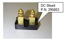
295003 DC Shunt
Product Support and Customer Service
For Further support visit our Contact Page
Required Materials
- Mounting Hardware
Required Tools
- Pliers
- Small Flat-Blade Screwdriver
- Multi-Meter
- Brass Brush
A DC Shunt is used to measure the current flowing through a cable connected to a load. The shunt is actually a high precision resistor and the output from the shunt is a small voltage, usually less than 100 millivolts. As the current changes, so does the voltage drop across the shunt. The shunt needs to be connected to a DC Ammeter that has been set up for use with the shunt. Note: Shunts are usually rated at their maximum point, e.g. 100 amps equal 100 millivolts, or 150 amps equals 150 millivolts.
Even though the voltage drop across the shunt is very low, the absolute voltage can be very high. In fact, it is the same as the present voltage setting of the DC rectifier.
The purpose of the fuse is to protect the equipment and employees in the event a short occurs in either of the two (2) shunt output leads.
Methodology:
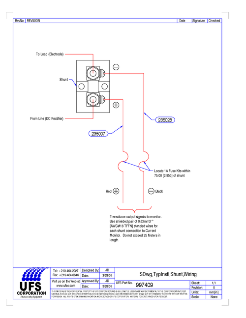
The shunt has four (4) connections; two (2) connections for the incoming power and load; and two (2) for the shunt signal. The shunt signal has a high and low lead (See Figure 1). The high shunt signal is on the power side (of the resistor) and the low shunt signal is on the load side (of the resistor). See Fig. 1 for illustration. Please read all the instructions listed below to familiarize yourself with the project before attempting to perform any of the work.
Think and act in a safe manner. Always disconnect power and use a lockout before you work on the E-coat system or any of the related subsystems. Observe any confined space conditions. Use the appropriate safety equipment & clothing for the task
Replacement:
1. Remove the ¼” brass nuts and washers from both sides of the old shunt. Remove both line and load cables from shunt.
2. If shunt was exposed to paint drips, use a brass brush on terminals and clean them to remove old paint.
3. Remove the signal cables with a flat screwdriver.
4. Remove the old shunt.
5. Place line cable over same post as before and attach the 6.4 mm (1/4”) brass washer and nut and tighten with pliers.
6. Repeat steps 5 for cable going to cell (load side).
7. Attach PN 235007 (Fuse Kit) to the same side as the line connection. This is the positive (RED, +) side of the shunt signal. This kit has a red sleeve attached to the wire to symbolize the Positive connection.
8. Attach PN 235028 (Fuse Kit) to the same side as the line connection. This is the negative (BLACK, -) side of the shunt signal.
Troubleshooting:
1. Cell is showing No current flow.
A fuse is blown or there is a loose wire.
2. Poor ED films.
Load cable has come loose from the load side of the shunt or the shunt element is blown.
3. Non zero value shown on meter face of Current Monitor Panel
Use a millivolt source and confirm that if say 30.0 millivolts is sent to the meter – then 30.0 should be shown on the meter. If not then investigate the meter setup.
Checkout Procedure:
1. Visually inspect the shunt and determine if the element is blown. Look for any evidence of black scorch marks. Replace as needed.
2. Use a Multi Meter to confirm that there is continuity between the Line (DC Rectifier) side and the Load (Cell) side of the shunt. An Open Loop (O.L.) represents a blown shunt element. Replace as needed.
3. Checking the Resistance value is also an effective procedure in checking the functionality of a shunt. However, the resistance value is very low (.001) and can only be detected with an ohmmeter that is rated for such a low value.
Related Topics
See Paragraph B under the Checkout Section of your Current Monitor Panel Getting Started Guide. This discusses the quality of the connections between the current Sensor and the Current Monitor Panel.
For more information see the original manual that came with the equipment or call UFSc at the phone number shown above.
BULLETIN 993406

