Calibration Power Supply Manual
Contents
- 1 Product Support and Customer Service
- 2 Safety
- 3 DC Voltage
- 4 AC Voltage
- 5 Front Panel
- 6 Rear Panel
- 7 Set-up
- 8 Adjust DC Voltage
- 9 Get Ready to Calibrate
- 10 Measure DC V
- 11 Measure AC V
- 12 Measure DC and AC V
- 13 Turn OFF the DC Output and AC Output when not testing
- 14 After the Calibration Data Runs are Completed.
- 15 Damage can Occur if…
- 16 Changing input voltage
- 17 Trouble-Shooting
- 18 Transformer 120 V AC Vs 220 V AC connections
- 19 Appendix
Product Support and Customer Service
For Further support visit our Contact Page
Safety
The power supply has an output as much as 265 V DC plus another ~24 V AC (RMS). So be careful and do not touch any of the exposed alligator clips - you will be shocked. =Purpose The use of the Calibration Power Supply is to offer a known voltage from which electrical test equipment can be calibrated with. It should be noted that the power supply itself is NOT calibrated. You will need to use a calibrated Volt meter (both DC and AC) and then adjust the output of the Power Supply to the proper voltage. Ratings
DC Voltage
The DC Voltage can be adjusted by use of the front panel potentiometer between 195 V to 265.
AC Voltage
This is meant to simulate the presence of AC Ripple. It is not adjustable. With 60 Hz power: 120 V AC yields an AC V of about 23.7 V AC RMS; with 220 V AC the value is only 20.3 V AC RMS.
Front Panel
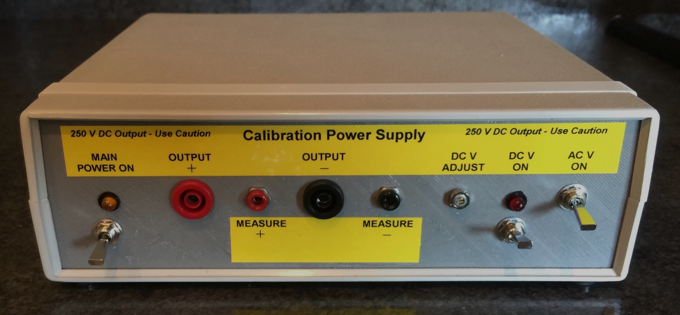
Rear Panel
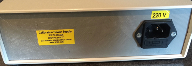
Set-up
The power cord plugs into the back of the unit and uses the IEC320-C14 standard receptacle used in many personal computers and other electronics products.Adjust DC Voltage
Tools needed: calibrated voltmeter with test leads, small 1.5 mm (1/16”) wide flat blade screw driver The first time you use the power supply you will have to: install the power cord, plug the power cord into the wall adapter, attach the red (positive) and black (negative) leads of the voltmeter, turn on the Volt meter, Turn ON the Main Power (left most switch), turn ON the DC V output (middle switch), measure DC voltage & adjust as needed with the small flat blade screw driver by turning the potentiometer clockwise or counter clockwise. Afterwards leave the power turned ON for at least an hour to allow it to warm up and stabilize. You may have to re-adjust the DC voltage a second time.
Note 1 – the voltage may drift a little if look at the tenths of a voltage. Do not be concerned about this very small variation.
Note 2 – There is no adjustment for the AC sine wave. In order to measure the Peak to Peak voltage use an oscilloscope. To measure the RMS (Root Mean Square) AC V then use an RMS meter to measure and record. When measuring the AC V do not turn on the DC output just the AC Output (right hand most switch).

Get Ready to Calibrate
Make sure the Main power is turned OFF before you proceed. You will need to attach the alligator clips to each of the voltage sensor tips first. In the photo below there is a 10 position voltage harness shown and each of the brass tips has an alligator clip on it. Then connect the Red banana plug to the Positive Output receptacle and the Black banana plug to the Negative (i.e. ground) output receptacle.
Measure DC V
Turn ON the DC V output and keep the AC output OFF. Record the reading on the calibrated volt meter. Then look at the voltage recorded by the data logger. Adjust the calibration of the Data Logger as needed.
Measure AC V
Next you can do another calibration with only the AC V ON. The TruIDL Logger does not have a calibration routine for AC V, so this information is for general review. The TruIDL Logger does not sample nearly fast enough to accurately measure the true AC sine wave. It is able to detect its presence and tell you generally if its more or less than 5%, which is the general upper limit for AC Ripple.
Measure DC and AC V
It is possible to turn ON both the DC Output and the AC output at the same time.
Turn OFF the DC Output and AC Output when not testing
When the testing is not done et but still more to do, turn OFF the DC and AC outputs. DO not touch any of the red alligator clips. Unplug the banana plugs first before you touch the alligator clips.
After the Calibration Data Runs are Completed.
When the testing is done turn OFF the DC and AC outputs. DO not touch any of the red alligator clips.
Now Turn OFF the Main Power switch and let set for a full 60 seconds. Remove the Red Banana plug carefully and then remove the Black banana plug from the front face of the panel.
Next remove the volt meter test leads from the front panel.
Now remove the Red alligator clips from the brass sensor tips and also the Black alligator clip from the ground clamp of the voltage sensor harness.
Damage can Occur if…
If the Red and Black leads are shorted together Do not allow any of the Red alligator clips to come close to the Ground Clamp or the Black ground wire
Changing input voltage
The power supply can be powered by 120 V AC or 220 V AC. Your unit was set-up for the voltage requested. If it necessary to change to the other voltage then contact UFS Corporation.
Trouble-Shooting
Blown Fuse
There is a glass 5 x 20 mm fuse located in the back panel power receptacle. Use small 1.5 mm (1/16”) wide flat blade screw driver to open the access port (remove the power cord first). For 120 V AC power use a 0.75 Amp fuse. For 220 V AC power use a 0.375 Amp fuse.
Transformer 120 V AC Vs 220 V AC connections

Appendix
Wiring Schematic

Product Drawing
BULLETIN 994424