New Generation Anode Monitor Equipment Manual
Contents
- 1 Product Support and Customer Service
- 2 Welcome to UFS Corporation
- 3 Introduction
- 4 Safety
- 5 Unpacking the NGAM
- 6 What is included
- 7 Equipment provided includes:=
- 8 Equipment supplied by Others
- 9 Description and Function
- 10 System Requirements
- 11 Basic Schematic and Diagram
- 12 Pre-Installation Planning
- 13 Installation
- 14 Software Installation References
- 15 Checkout
- 16 Quality Assurance
- 17 Operation
- 18 Maintenance
- 19 Warranty and Liability
- 20 FAQ's / Trouble Shooting
- 21 Drawings and Schematics
- 22 Installation Checklist
Product Support and Customer Service
For Further support visit our Contact Page
Welcome to UFS Corporation
This guide is intended to be an overview of the NGAM Panel (evaluates current passing through a typical Membrane Electrode Cell) and how it works. It is presented to the owners, system designers, installers, and members of the paint-finishing department where the equipment is to be used. It is important that you keep this documentation in an easily accessible place for future reference.
Introduction
This guide provides general instructions for installing, operating, and maintaining a New Generation Anode Monitor (NGAM).
Safety
A safe work environment for our customers (their employees and outside contractors) is of utmost importance to UFS Corporation. All applicable OSHA and owner’s safety requirements must be followed when performing any maintenance, inspection, repair or testing on Electrodes and/or Electrode Systems. This includes, but is not limited to, the following safety regulations: Lockout/Tagout (Energy Control); Hazard Communication; Confined Spaces; Personal Protective Equipment; Electrical Safe Work Practices; Ergonomics and Material Handling; Accident Prevention signs (Danger – Energized Equipment). Before installing or working on the DC rectifier, Lockout/Tagout procedures are to be followed. Use a Splash Guard (UFS PN 175101 or equal) on top of the Electrode Holder / Membrane Shell with ED tanks that do not have an enclosure wall surrounding the Electrodes. Ongoing training of employees on E-coat equipment and system installation, operation, and maintenance of UFS components is strongly recommended. MSDS (Material Safety Data Sheets) are provided for UFS materials. Replacement or missing copies are available upon request from the UFS Safety Coordinator.
Unpacking the NGAM
Carefully remove the packing from around the outside of the panel. Loosen the screws at each corner of each panel.
What is included
Touch Screen PLC

Previous versions used a smaller touch screen. Starting in 2016 the touch screen was increased to the Vision V1210, which ~12 inches across. Some of the picutres later in this document show the smaller Vision PLC from Unitonics.
Hall Effect Sensor
Panel

Equipment provided includes:=
Panel with PLC (If more than one panel is included then this is called ‘Host Panel’) Remote I/O Panel #1 (if included) Remote I/O Panel #2 (if included and so on) Documentation Current Sensor (one for each ME Cell or Bare Electrode) 2 x 2 GB SC cards with USB Reader USB adapter for SD Cards RS232 programming cable (DB9 male to RJ-11) For small systems there will be only one enclosure. The PLC and all I/O modules will be located in this. In larger systems there will be a need to break the I/O modules up since there is a limit to how many can be directly connected to the PLC. In this case the Panel with the PLC will be called the Host and the other panel(s) will be called Remote #1, #2, and so on.
Equipment supplied by Others
The construction related parts will have to be supplied by others. This list includes, but is not limited to the following items:
- Belden 5501FE, or equal used for DC Current sensors
- Belden 8724, or equal, for CANBus wiring of Host Panel to Remote Panel(s)
- Twisted pair 22 Gauge Plenum cable for signal conditioners located in each DC Rectifer
- 110/230 V AC power supply cable
- Conduit, fittings, & hardware
- Ethernet cable & connectors, outlet, et al
- Mechanical parts to support conduit and the NGAM enclosure
Description and Function
Electrodeposition (E-coat) coating is an electrically driven painting process. The amount of electrical current delivered, over time, determines how much paint film is deposited. Thus, each different ware may take a different number of Coulombs (i.e., amp x seconds) in order to have the proper amount of ED film thickness.
To measure how well an ED system is working, it is helpful to take a look at the output ammeter of the DC power rectifier. If the current is low, film thickness may also be low. Since the electrocoating circuit is wired in parallel with the DC rectifier, the individual current flowing through each Anode Cells becomes more important in determining the overall performance of the ED System. The total current displayed at the DC rectifier tells the operator that the rectifier is working but says nothing about how that current is distributed among all the Anode Cells or Bare Electrodes.
The NGAM is well suited to quickly display current flow values for monorail type systems. There is a moving conveyor line and the current (for any given cell) will reach a peak as the ware crosses in front of it. For hoist type systems it is difficult to determine the peak current value of more than one cell in each paint cycle. However, the NGAM will still provide current flow for each cell and serve as a spot check tool.
The PLC has an SD card and process data will be saved on to the card at various intervals. This card can be removed and data can be transferred to a hard drive on a corporate network for permanent record keeping and creation of long term trend charts.
The Human Machine Interface (HMI) screens are designed to give the operator a lot of data in such a way that it is easy and quick to understand. The real time DC current for each Cell is always presented. Further, there is a color coded dot that tells if the current is normal, low, or high. With time the operator’s attention will be directed at those Cells that are NOT normal to determine if action is required to bring the Cell into the normal range once again.
For more information see the FAQ’s section at the end of this Manual.
System Requirements
- 3 amp, 115 V AC to 220 V AC power for each Panel(s).
- For using the remote access programs from Unitronics a Windows PC with an Ethernet connectoin is needed.
Basic Schematic and Diagram
See Appendix A for personalized Schematic of Panel (i.e. Host Panel in some cases) and Remote Panel(s). A copy of your panel wiring diagram is included inside the front dorr of the enclosure.
Pre-Installation Planning
Some easy planning steps will result in a better installation and more satisfying results.
Anode Cell Numbering Scheme
Establish a numbering scheme so each Anode Cell has a unique number or code. This numbering scheme will then be used to match location of Anode Cells with the numbers shown on the HMI screens on the front of the NGAM Panel.
Monorail and Hoist Systems
Begin the numbering sequence at the entrance of the ED tank. Select one of the entrance cells (either side is fine) to be #1. The opposite cell will then become #2. The second cell behind #1 will become #3. The second cell behind #2 will become #4 and so on.
Ease of Use
The purpose for the numbering scheme is to provide assistance to the person doing the observing. In either case, the numbering scheme will ensure the #1 cell is across the ED from the #2 Cell. Cell #3 is across the ED tank from Cell #4 and so on. This way the current should match up for #1 and #2 and so on for each successive pair of ME Cells that are opposite each other in the E-coat tank.
Panel Location and Conduit Sizing
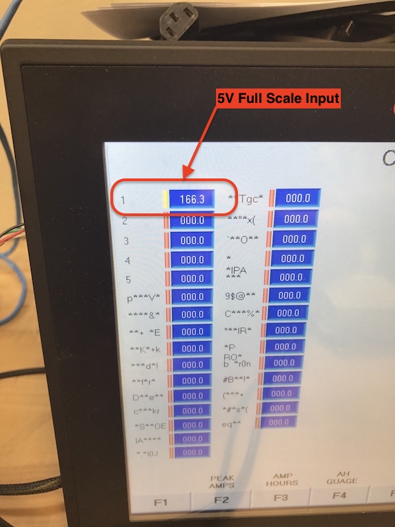
The voltage signal generated by the DC Current Sensor is usually 2.5 V (Vsupply / 2) when there is no current and almost 5 V (i.e. Vsupply) at 166 amps (using 15 mV/amp sensitivity). The length of the transducer cable that carries this signal is limited to about 25 meters (80’). If the run is much longer, then perform a test with a long piece of cable and inject a 2.5 V voltage signal source into the far end. Use an accurate voltmeter to read the signal on the other end. If the results are close, the test will be successful. During the test period be sure to include a maximum amount of electronic interference (welding, radio traffic, motors, etc.) to be present to increase the confidence of the results.
Convoy Conveyor System
A good place to locate the NGAM Panel is on the front end of either side of the ED tank enclosure wall. The conduit from the other side can be located under the front nose of the ED tank, which will shorten the cable run length.
Hoist System
Generally the NGAM will be placed on one of the short ends of the ED tank (perpendicular to work flow).
Electrical Codes
Make sure to abide by all the applicable local, state, and federal electrical codes.
Installation
The NGAM Panel installation is comprised of mechanical support, electrical installation, and cabling.
Mechanical Support
NGAM Panel
The NGAM Panel should be mounted at eye level so personnel in the plant can easily reach all the controls and see the readout. All conduits with shielded pairs should be brought to this location and holes punched into the NGAM Panel.
DC Current Sensor
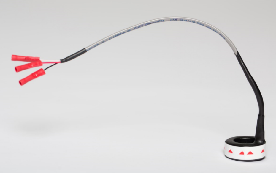
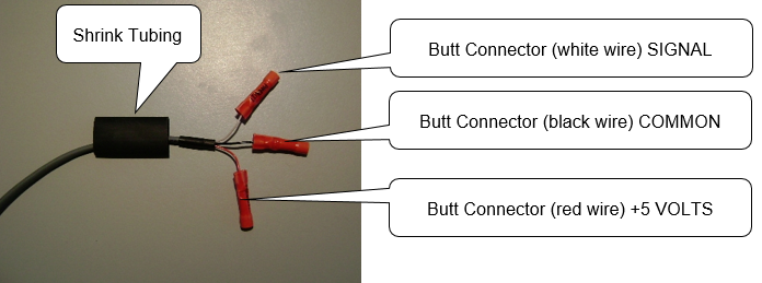
The DC Current Sensor is installed on each Anode Cell cable lead. Remove the cable from the Anode Cell and pass it through the center of the sensor.. Make sure the arrow on the Sensor is pointing at the Anode Cell. Re-connect the cable with the Anode Cell Anode. The sensor has a 30 cm pigtail with 3 wires (red is +5 volts, black is common, and white is signal) with AWG 22 gauge butt connectors.
The sensors are best placed inside a distribution panel with a spacing of about 25 mm (1 inch) to another sensor or another conductor. Alternatively the sensors can be placed closer to the anode cells. A couple of pre-cautions are requested: place the sensors to they will not be stepped or otherwise damaged; and placed in a dry location with no spray mist.
It should be installed on a horizontal portion of the Anode Cell cable. Use some foam tape, or equal around the conductor so the conductor is centered in the toroid. This insures the magnetic field is properly captured by the toroid and any leakage of the magnetic field is less than 2%.

Use a plastic wire tie to secure the wire lead of the sensor assembly to the conductor cable as shown below.
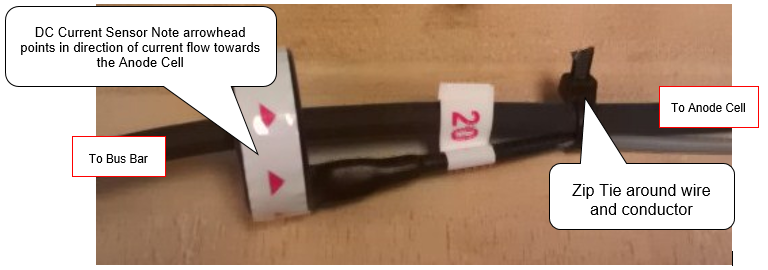
Important Note – the red arrowhead must be pointing towards the Anode Cell. It will not work if the arrowhead is pointing towards the DC rectifier.
Electrical Installation
NGAM Panel
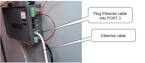
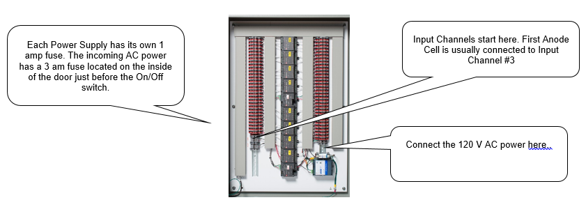
Provide 120 VAC x 3 amp service to the NGAM Panel(s)s AC input terminals. Ensure that the NGAM Panel enclosure is grounded to a good earth ground. Connect PLC to your (see picture below) Local Area Network via a Category 5 or 6 Network. Please consult your Company's Network Administrator for additional requirements and network accessibility.
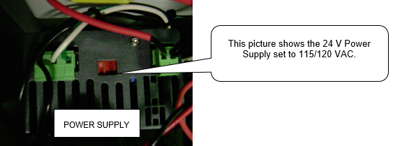
'''Important Note about 220 V use''' The power input selector swtich on the 24 V DC power supply must be pre-selected before power is turned on as shown below.
Connect 0-10 V Signal from DC Rectifier
Run an appropriate cable from the DC rectifier to the first input channel. Note 10 V equals the full output of the DC rectifier. Note the 5 V power supply has been factory wired into the second input channel.
Connect Sensors using Belden 5501FE
Each DC Current Sensor needs to be connected to the NGAM Enclosure. Use the Belden cable or equal. The Belden cable has a 4th conductor for the shield (drain). Do not cut this shield conductor off. Keep this shield connection for future use, if there is significant noise and the decision is made to connect all the shields to the earth ground inside the NGAM enclosure.
Hardware Set-up
24 V Power Supply
Select the proper input voltage for the 24 V DC power supply in each panel. The default setting is 115/120 V AC. The 5 V DC power supply has an auto select function as long as the power is 115 to 230 V AC.
Software Installation References
Please visit Unitronics Support page located at www.unitronics.com for installation support and procedures.
Remote Access and Remote Operator
Obtain the most recent version of Remote Access and Remote Operator Software at Support on www.unitronics.com. For User Manuals (Remote Access and Remote Operator) please visit the Technical Library on Unitronics web site. Both programs are similar. Remote Access is an older program and is somewhat primitive. We suggest you start with Remote Operator. Note only ONE PC can be connected to the PLC at one time.
SD Card Suite
Please visit www.unitronics.com for the SD Card Suite software downloads. This can be located on their support page under downloads. You must use this utility program to FORMAT the SD Card being used. DO NOT USE WINDOWS TO FORMAT SD CARDS for use in the Vision PLC.
Checkout
After all the installation steps are completed, it is time to test and debug the field wiring to look for shorts and poor connections. If there are problems, refer to the Troubleshooting section. Use the form in Appendix C to oversee the installation of hardware. If UFS personnel cannot be at the site for all of the installation, then fill out this form and send it to UFS for assistance in start-up.
PLC Display
Turn on the Host and Remote Panels (if so provided). The Unitronics splash screen will show up followed by a hardware status screen and the home HMI screen for the program that was provided.
Home
From the home screen you can navigate to: View Cell Status; View Cell Ah; or Configure.

View Cell Status
This shows you the real time current for each Cell or the most recent peak value.
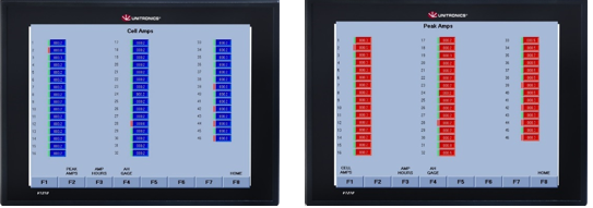
The # to the left is the Cell ID #. In the Cell Amps screen there is a bar to the left of the value (blue box). If this bar is red, then the value in the blue box is below the ‘Green Low limit’. If this bar is yellow then the value is above the ‘green High Limit’. If the bar is Green, its in the normal range.
View Cell Ah
On this HMI screen you will see the Ah (i.e. Amp-hour) tall for each Cell. It can be viewed as a bar graph or a total.

Configure
From this screen you can see the Excitation voltage (i.e. 5 V power for the Hall Effect current sensors and the DC rectifier voltage. The low end of the Green range and the high end of the Green range needs to be established. You can also set the date and time too.

TCPIP Settings
Enter the static IP address for the unit per your Network Administration
Factory Config
Access to this page requires a passcode
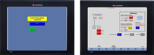
Once the passcode of ‘2222’ is entered you are shown a screen with 4 options: Hardware Setup; A-H Setup; Calibration; and Cell Enable.
Convoy (Monorail) Setup
Press on ‘Report Period’ and enter a value from 0 to 327 seconds. Data will be written to the SD card based upon this value. Peak values are also reset based upon this too.

Max Rectifer Voltage
A 0-10 V signal from the DC rectifier is required (usually to the first I/O channel of the PLC), where 10 V = the max rectifier output (this voltage vlaue is filled in the dark blue region, by presssing on it and entering the value).
Sample Period
This has a range of 0.25 sec to a maximum of 2 seconds. It is recommended to keep this at 0.25 seconds. This means that there will be four reading for every seond of operation, or 240 readings every minute. The faster sample rater will make the the Amp-hour tally be more accurate since the readings are taken so close together, thus the error will be small.
# of Cells
This is for UFS Factory use only.
Hoist Setup
The preferred method is ‘Volts’ and this requires a 0-10 V signal from the DC rectifier, where 10 V = the max rectifier output (this voltage vlaue is filled in the dark blue region, by presssing on it and entering the value). Refer to above for how to setup the 3 parameters on the right of the screen.

For ‘Volts’ use 10 V to start ‘logging’, and 5 V for the end of the E-coat paint cycle. For the ‘Amps’ method enter a start value of 5 Amps and an Ending value of 2 Amps. In this case the Amp-hour tally will begin once any Cell has more than ‘Start’ value and the E-coat apint cycle will be considered finished when the last Cell falls below the ‘End’ value. If a sensor fails to ‘turn off’ once the rectifier goes to zero volts, then these Cells’ sensors must be de-selected (Cell Enable screen) otherwise the Amp-Hour tally will be greatly over-stated.
Cell Enable
This screen allows you to dis-able a sensor if it hangs open, which means it reports a current when the DC voltage is zero. It is important to trouble shoot the matter and get the sensor repaired or replaced quickly so the Amp-hour tally for this anode cell is kept as current as possible.

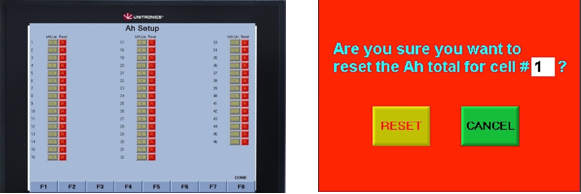
A-H Setup
This screen should only be touched by the supervisor since you can lose the accumuulated Ah figures if you are not careful. When a Membrane Sheel is replaced with a new Shell. It is time to reset the Ah tally since the old one (with the Ah data) has been replaced with a new one. For example, the Membrane Shell for Cell #16 was replaced today. The Ah tally for Cell #16 should be reset today. Press the yllow ‘R’ for Cell #16 and you will see the red screen sdaying that Cell #16 will be reset ‘Are you sure you want to continue? Thre other data you can enter is the Ah setpoint for each Anode Cell. Call UFS Corporation if you havev a question abuot what is the Ah limit for the Cell(s) you are using.The last three digits are not entered. If the number if 1,500,000 Ah then you would enter this as ‘1500’ (last three zero’s are not entered)
Calibration
Accept the defaults shown under ‘Default Sensor Values’ as shown below. With the Rectifier voltage at zero (i.e. there should be No Current flowing) press the blue button. This will establish what ever voltage is being reported by each of the sensors, ‘this value = Zero’. Do not change '2500 mV @ 157 Amps'.

The yellow button should only be used under special conditions at the direction of UFS.
Current Sensor Wiring Testing
With no current flow to the ME Cells, the PLC should show zero’s. Check to make sure the sensor has 5 V DC power supply and the common connections are ok. If the value shown is ‘-1’ then this Cell has been ‘de-selected’ and its’ sensor needs repaired or replaced.

Quality Assurance
In the back of this Guide is a copy of an Inspection and Certification report. All product(s) are tested and certified before they leave the factory. The matters of the testing and the results are shown on this report. Please refer to the Q/A
Operation
NOTE: Please read all of this Section, the "Maintenance" and Troubleshooting" sections before beginning operation. The "Troubleshooting" section explains the most common NGAM Panel problems.
Touch screen
The PLC is equipped with a high end Touch Screen interface. Please make sure your hands/fingers are clean. If screen becomes dirty please use a cleaner designed to clean LCD Monitors/Screens found at your local office supply store.
Current values are not steady.
Current readings will probably not be steady. They will either cycle from a low reading to a high reading for a Convoy type ED system. (This assumes a steady state voltage set point.) The time from the low to the high and back to the low will approximate the jobs per hour that are painted in the ED system. On the other hand, for a hoist ED system, the current will quickly rise (after voltage is turned up), but then start to fall off after about 3 to 5 seconds. From this point on, the current will continue to decline (as the ED paint film builds and insulates) until the voltage is brought back to zero.
Other factors that affect current.
The goal with continued use of the NGAM Panel is to construct a trend line chart of the performance (current draw) for each Cell. If the current draw for a Cell is significantly down (compared to previous readings), corrective action should be taken. The following is a list of other factors that should also be recorded at the time amp readings are taken: voltage set point, ED bath temperature; change in painted area of largest part. The life of the ME Cell is going to be affected by the amount of DC current it delivers to the E-coat bath over its lifetime. Thus the more ‘real time’ the current data is, the more accurate or representative the data will be. As a note, the more data collected (hoping to capture the ‘peaks’) the larger the file sizes and the longer it takes Excel to open and process the data. Accurate date = larger file size
Raw Data Collection
Data saved to the SD card includes the following:
- Date
- Time
- Peak Voltage
- Peak Current for each Anode Cell
Convoy Conveyor type (i.e. Monorail)
The recommended ‘Save to SD card’ interval should be set to 300 seconds (5 minutes). Peak data will be saved every 5 minutres..
Hoist
A hoist system set-up will only record to the SD card once the cycle is completed and only peak data is saved.
How often to remove data from the SD card?
Every month or so would be ideal, as long as the file size does not get too large, which they should not given you use a 16 GB SD card, or similar.. We ask you to remove the card after a couple of days of operation and send UFS a copy of the raw data file. We can then know how large the data file is and what is a good interval to download the data to its permanent storage location (plus a back up copy kept somewhere else too). Please we can confirm the value being recorded are in the normal range. It is possible to write a script that can automatically reach into the SD card and copy (rename with a date code in the new file name) the data to the storage location, make a copy at the back-up location, and then erase the SD card. A note about the format of the data on the SD card: The data is written in CSV format; meaning each value is separated from the next by a comma. After the last number is written a carriage return is entered and a new line (i.e. record) is started. Raw data files should be placed into a folder that is read only and cannot be changed or altered in any form.
Downloading Raw Data Files from SD Card
To transfer the Raw data files, remove micro SD Card from Panel and place into provided micro SD card reader. Place the reader into a USB port on your PC. Copy the UFS.CSV (raw) to (2) locations on your PC. UFS.CSV should be located in the Excel #1 folder on the SD card. One copy should go into a folder that will maintain ‘all the raw files’ (complete history). Rename this file to something that would represent the time that card has collected data (ex: 05jun112_thru_12jun112.csv) making sure to keep the file extension CSV. Save another copy to a suitable backup place so you always are keeping a minimum of (2) copies of the raw data. The third copy can be placed on your desktop. You can keep this file name the same. You will need to keep this file after you have extracted a typical record for each day on the file. Once this is done and you can place the SD Card back in the (HOST) Panel.
Historical Summary Spreadsheet
Open the most recent UFS.CSV file (the one on your desktop from steps above) using Microsoft Excel. Within this file, you will want to cut and paste over to another Excel file where you can make trend plots and print reports. Create an Excel file (each year start a new file to keep the file size manageable) called “Your Ecoat Name” Historical Current Data.XLS") and paste each new portion of data into this spread sheet, Once copied,you can delete UFS.CSV on your PC desktop (making sure you have the other copy in a safe location for archiving). You will go through this procedure every time you remove the SD Card to have an ongoing spreadsheet. You have the UFS.CSV files (raw) for record keeping/archive of past history of ALL data. UFS will also provide a 3rd party solution called DAQfactory and some of the SD card record keeping may be superseded by the database functions included in DAQfactory. Typically DAQfactory will be delivered several weeks after the installation and successful start-up of the PLC.
Maintenance
The routine maintenance required for the NGAM Panel is minimal and there is no suggested maintenance schedule. If problems occur, the remainder of this section can help. Read the section on Safety before performing any work on the panel.
Open Panel Door
Open the door slowly and make sure cables are free to move. Take care not to touch any 120/220 V power wires, they will shock you!
Inside Host Panel Door

Inside Remote Panel Door

Suspected Wiring Faults
If an internal wiring fault is suspected, then refer to the appropriate panel wiring drawing for the NGAM Panel located at the end of this guide and on the inside of the front door.
Suspected Current Sensor Faults
A sensor fault will show up in two ways: either it stays at zero and never show any results other than zero; the other fault will be when the sensor hangs open and says there is current even though the DC rectifier is turned off. The number may be say 140 or maybe even lower, but it does not change at all. Check to make sure 5 V is being sent to the sensor and there is no current flowing through the sensor. The voltage on the white lead should be ½ or about 2.5 V. If this is not the case, then the sensor has been damaged and needs returned for inspection and repair. If the readout for a Cell shows ‘-001.0’ then this Cell has been de-selected. Refer to the section on Maintenance/Factory Set-up/Cell Enable.
Fuses in power supply outputs
The 24 VDC and 5 VDC power supply are fused using 1 amp blade style fuses. In addition there is a 3 amp fuse on the incoming 120 V AC power.
Warranty and Liability
Warranty
We warrant all equipment manufactured by us to be free from defects in material and manufacture at the time of shipment for a period of one (1) year from the date of shipment. We will furnish without charge F.O.B. our factory, but will not install, replacements for such parts as we find to have been defective. This warranty shall not apply to any equipment which has been subjected to misuse, neglect or accident, or has been altered or tampered with, or if corrective work has been done thereon without our specific written consent. No allowances will be made for such corrective work done without such consent. Improper maintenance, deterioration by chemical action, and wear, do not constitute defects. Equipment manufactured by others, and included in our offering, is not warranted in any way by us but carries only the manufacturer's warranty, if any. All electrodes (and or cathodes), of any material, are not warranted by us in any way since they by nature are sacrificial and will erode or corrode away with time. All warranty claims must be submitted within ten (10) days of discovery of defects or shall be deemed waived. All parts returned for inspection must be sent prepaid. No representative of our company has any authority to waive, alter, vary or add to the terms hereof without prior approval in writing. The foregoing is in lieu of all other warranties (including that of merchantability), whether express or implied.
Liability
It is expressly understood that our liability, including that for breach of Contract, negligence, strict liability in tort, or otherwise, for our products is limited to the furnishing of such replacement parts, and that we will not be liable for any other expense, injury, loss or damage, whether direct or consequential, including but not limited to loss of profits, production, increased cost of operation, or spoilage of material, arising in connection with the sale or use of, or inability to use, our equipment or products for any purpose, except as herein provided.
Manufacture Manuals, Links and Specifications
Vision OPLC Technical Specifications (for PN V570-57-T20B)
I/O Expansion Module Adaptor (for PN EX-A2X)
I/O Expansion Module (for PN IO-ATC8)
24VDC 3A Power Supply (for PN PS24-075D)
Switching Power Supply 5VDC 4A 20W (for PN PSP05-020S)
110V Clear Lamp (bulb) (for PN ECX1904-5)
1A Fuse ATC Style (for PN BUSS ATC1 & ATC3)
3A Fuse ATC Style (for PN BUSS ATC1 & ATC3)
FAQ's / Trouble Shooting
Zero reading when the DC rectifier is On. Check to make sure 5 V is being sent to the Sensor.
When no current is flowing there should be about 2.5 V in the white signal wire. Also make sure the arrowhead on the current sensor is pointing towards the anode cell.
If a sensor reports a value even when the DC rectifier is turned off then the white and red wires may be shorted together.
In this case the sensor should be ‘de-selected’ so the amp hour tally is not over-stated while it is repaired/replaced.
SD card is not recognized by the PLC.
Make sure the SD card was formatted by the Unitronics SD Carte Suite.
No indicator light on REMOTE PANEL
Check to insure power is supplied to unit. If power is present, replace bulb. See Spare Parts List for correct Part Number.
Display not visible
Touch screen to activate display. If display does not come on, check the fuse for the 24V output for the power supply.
Remote Offline Indicator light flashing
Check to make sure power is supplied to remote panel. If power is present, check the CAN BUS connections.
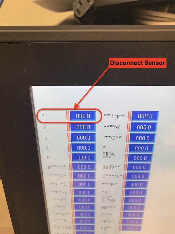
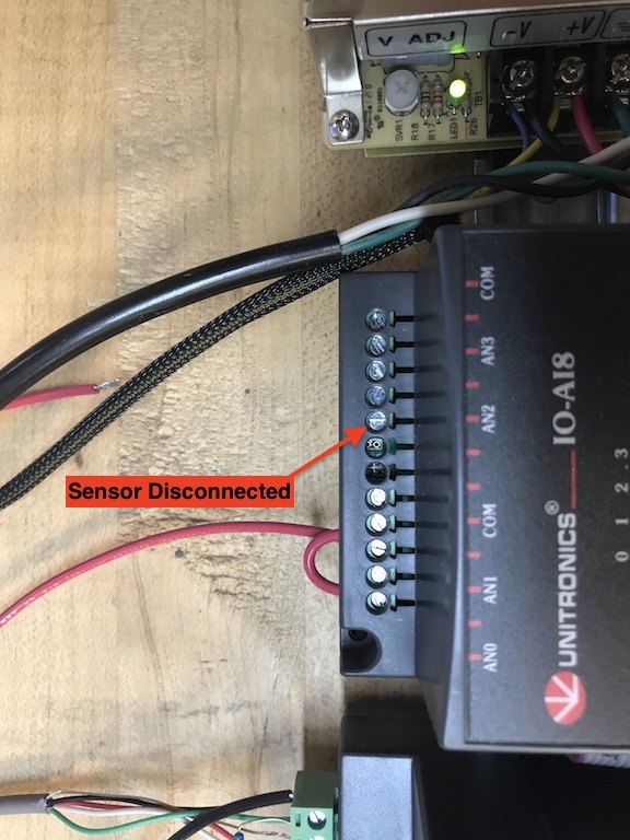
What happens when an input to an IO module (DC Current Sensor) is a removed?
If the sensor is removed then the display should read zero, since the input would be 2.5v or less. (see images below)
Drawings and Schematics=
Panel Drawings
Wiring Diagram
Installation Checklist
New Generation Anode Monitor Installation Checklist
BULLETIN 994411