Replenishment E-coat Paint Feeder System
Contents
- 1 Product Support and Customer Service
- 2 Process Schematic
- 3 Space Planning
- 4 Paint Feeder Hardware
- 5 ARO Piston Pump
- 6 ARO Diaphragm Pump
- 7 Pump Setup
- 8 Piston Pump
- 9 Tote / Piston Pump
- 10 Pump Suction Kit
- 11 Test Pump
- 12 Amp Hour Controller
- 13 Amp Hour Calculation
- 14 Amp Hour Controller Setup
- 15 Static Mixer
- 16 Not Included
- 17 Start Up
- 18 Maintenance
Product Support and Customer Service
For Further support visit our Contact Page
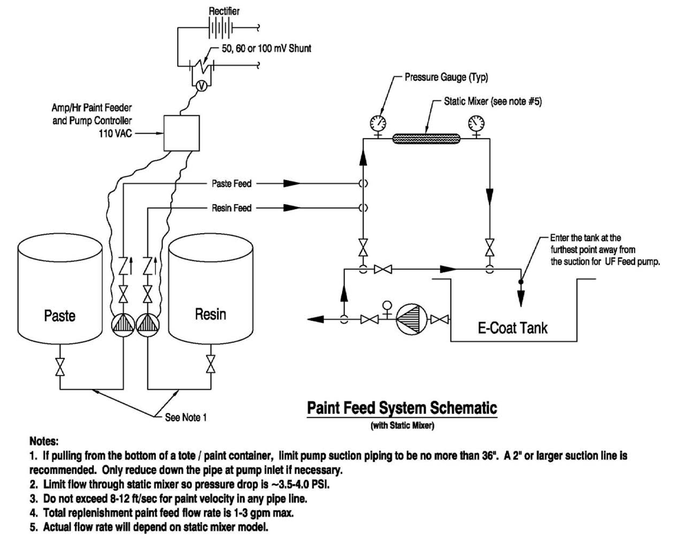
Process Schematic
Space Planning
Totes
Make sure there is space for a fork truck to move a new one in and remove the old one
Drums
Hand truck or fork truck maneuvering room? Drums using diaphragm pumps should have two positions so pump suction and agitator can be removed and quickly placed into waiting drum.
Paint Feeder Hardware
- JP Tech brand Amp Hour Controller receives current data from the DC rectifier's shunt to control one or two pumps
- If using 2 rectifiers, order appropriate model
- ARO brand 3” Air Motor, 4:1 Ratio 2 Ball stainless steel piston pump, wall mounted, magnetic proximity sensor for stroke counting.
- Use one pump per component
- KoFlo brand flanged 2” PVC static mixer, 12 mixing elements, 3.5 psi pressure drop at 25 gpm
- 2” side stream pipe system is used to inject replenishment paint
ARO Piston Pump
- Model NM2304B-11-311
- 8.2 in3 (134.3 ml) per cycle
- 28.2 cycles per gallon (7.4 cycles/liter)
- Max cycles per minute = 125
- Flow rate at 60 cycles/min� 2.1 gpm (8.0 l/min)
- 85 dBA @ 100 psi inlet pressure
- Air inlet pressure: 0 – 150 psi (0 -10.3 bar)
- Fluid pressure at discharge: 0 – 600 psi (0 – 41.4 bar)
- Use enough inlet air pressure to overcome pressure in side stream piping.�
ARO Diaphragm Pump
- Model PD10P-APS-PAA
- 1:1 ratio (discharge pressure = air line pressure)
- 0.226 gal (0.86 liters) per cycle
- Pump weight 19.6 lbs (8.9 kg)
- 60 cycles per minute @ 70 psi
- Max Flow rate� 53 gpm (200 liters/min)
- 79.9 dBA @ 70 psi inlet pressure
- Air inlet pressure: 20 – 120 psi (1.4 – 8.3 bar)
- Important note - use enough inlet air pressure to overcome pressure inside paint injection stream piping.�
Pump Setup
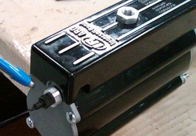
- Install magnetic proximity sensor
- Install electric solenoid valve
- Install the air filter/regulator
- Add a high pressure line to the solenoid valve
- Set pump into its wall mount bracket
- Attach 2” suction line, limit length to 5’ or 6’
- Attach appropriate discharge line
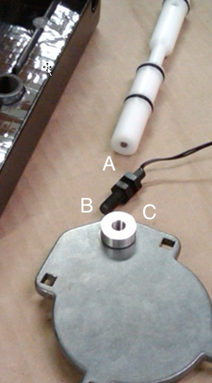
Piston Pump
- Stainless steel
- Solvent cup provided
- (A)Magnet is inserted into the spool piece
- (B & C) Magnetic proximity sensor is threaded into aluminum adapter in Top Cap
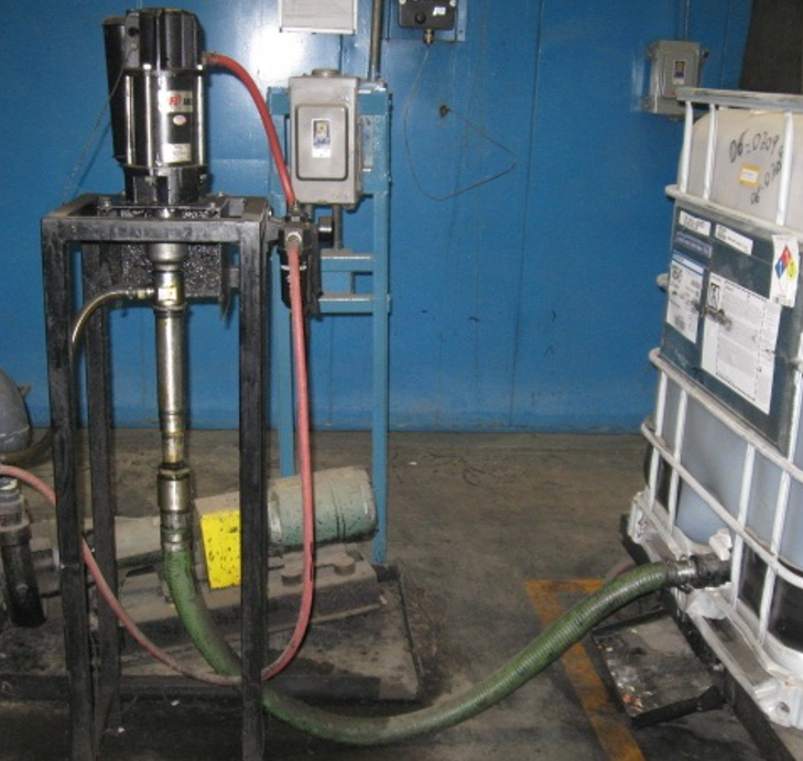
Tote / Piston Pump
- Note - customer made this frame from included wall mount adapter
- Pump discharge is ¾” NPT
- Reduce suction to 1-1/4” NPT at pump
- Keep pump suction same as tote discharge and about 3 ft long
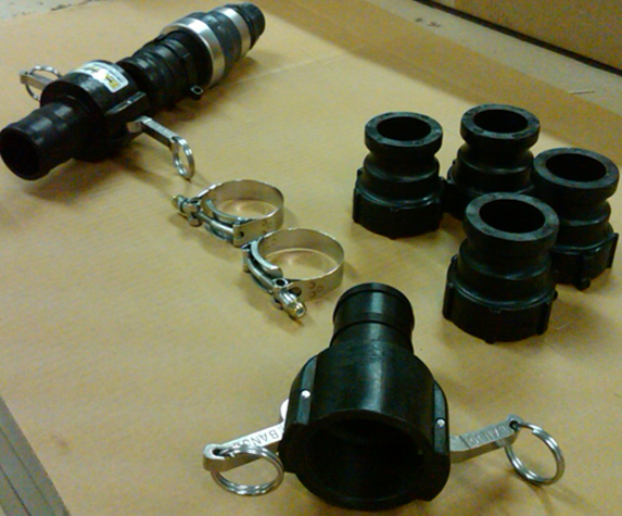
Pump Suction Kit
- Attach fitting to pump suction
- Thread male camlock adapter into fitting
- Thread other male camlock adapter to the discharge of the tote
- Measure the distance and cut 2” flex line, allowing some slack.
- Use the band clamps to secure the flex line to the camlock hosebarb adapters
Test Pump
- Confirm discharge of paint per complete pump cycle
- Measure time required to add required # of strokes
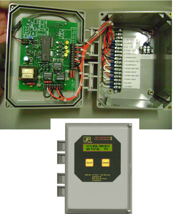
Amp Hour Controller
- Input from rectifer shunt
- 110 VAC power input
- Output to control pump via air solenoid valve
- Input from pump to count strokes via magnetic proximity sensor
- Mount at eye level
- Requires 110 V AC power input
- 110 AC voltage is also used to control operation of the pumps via solenoid valve(s), by a wire from the solenoid valve(s) to the terminal strip
- Wire the magnetic proximity switch(es) to the terminal strip
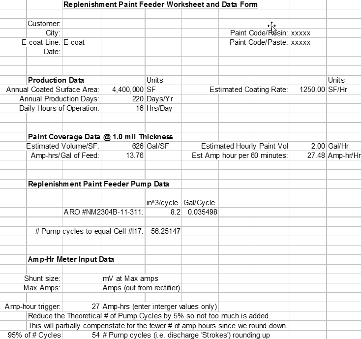
Amp Hour Calculation
- What is typical SF of ware per hour?
- What is the annual production?
- How many days per year?
- How many hours per day?
- What is theoretical volume of paint at required film thickness?
- How many SF will one gallon cover at 1 mil?
- How many amp hours are used to coat 1 gal of paint?
- What is discharge of piston pump?
- How many pump cycles are required?
- At a given supply air pressure, what is the elapsed time to deliver all the strokes?
Amp Hour Controller Setup
- Shunt size and maximum amps of each rectifier
- Amp hours when paint will be added
- Strokes (i.e # of pump cycles required)
- Enter time required to add the necessary # of strokes (this is used by the controller if the stroke count sensor fails)
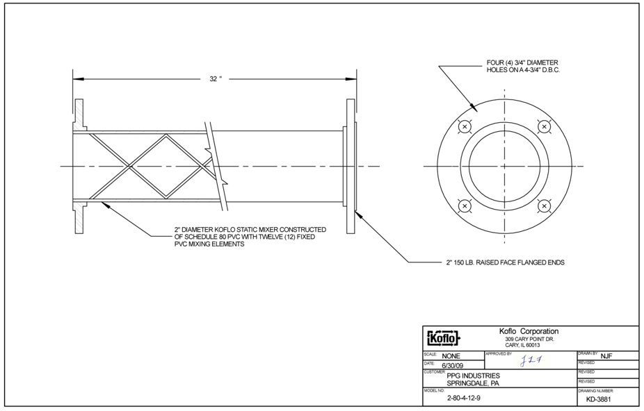
Static Mixer
- 2” pipe size
- Limit flow rate through static mixer so delta P does not exceed 4 or 5 psi
Not Included
- Wiring, conduit, fittings of Amp hour controller.
- Air supply lines to air motor
- Floor mount/support stand if wall mount is not a suitable support structure
- Discharge piping from pump to side stream piping
- For 2 component paint: 2 check valves, PVC piping & fittings, 3 ball valves (2 @ 2” and 1 @ size of existing paint pipe that replenishment paint will be injected in), 2 pressure gauges, 2” PVC pipe.
- For 1 component paint: 2 check valves, PVC piping & fittings, 2 ball valves (2 @ 2” and 1 @ size of existing paint pipe that replenishment paint will be injected in), 1 pressure gauge, 2” PVC pipe.
Start Up
- Review paint feeder worksheet with your paint company & UFS
- Verify volume discharge per stroke
- Confirm programming of Amp Hour controller
- Tell controller the size of the shunt (i.e. milliVolts at max amps) & max amps
- Input the number of strokes required for the # amp hours desired (the fewer the # amp hours desired the more often the pump will operate)
- Measure the time required for the pump to operate the requested # of strokes
- Input this into the Amp Hour controller as a fail safe in the event the stroke count suffers a sensor failure and pump is then controlled on a time basis
- Measure %NV twice a shift for first week of operation and verify the # strokes and adjust as required.
- Use a portable flow meter to verify 25 gpm in the side stream and mark the pressure gauges for normal operation
Maintenance
- Air operated pumps have moving parts, so inspect & be prepared to replace per manufacturer’s PM recommendations
- Air motor replacement parts kit included
- Pump end replacement parts kit included
- Calibrate pressure gauges in the side stream and verify flow once a year with portable flow meter
BULLETIN 994121