Anode Area Calculation
Product Support and Customer Service
For Further support visit our Contact Page
General
Anode area can be determined by using several different methods and then reviewing the results to make an informed decision. These methods include the 4-to-1 rule (most commonly used; is based on a 2 minute dwell time), the 2.5 minute rule, average Anode current density, and Cell center-to-center spacing. If your E-coat system has less than a two minute dwell, or the film build is greater than 25µ (1 mil), the 4:1 rule will undersize the Anode area required. Conversely, if your system has more than a two minute dwell, or you want to apply less than 25µ (1 mil), the 4:1 rule will oversize the required Anode area. In these instances, use the Anode current density method to provide better results.
Data Collection
The first step is to gather pertinent E-coat system information, including operating parameters, E-coat tank parameters, and E-coat tank dimensions. The information requested in Sections B and C of the E-coat Tank Survey (Bulletin 999101) serves as a good outline for completing this step.
4:1 Rule
The 4-to-1 (ware area-to-Anode area) rule was developed from empirical data and provides a very suitable result if the E-coat system has two minutes of “power-on” dwell time and the user wants to apply 25µ (1 mil) of E-coat film.
Work Area Basis:
The “Work Area Basis” (WAB) is the area that passes in front of an Anode Cell in two minutes. (Two minutes is arbitrarily selected for the purposes of calculation, and thus is fixed regardless of your actual dwell time.)
Anode Area Basis:
Divide the WAB by 4. The result is the suggested amount of Anode area, or “Anode Area Basis” (AAB).
2.5 Minute Rule:
Used by some automotive E-coat systems, this is a variation of the 4-to-1 Rule. It results in 25% more Anode area because the AAB is calculated using 2.5 minutes rather than just 2 minutes.
Average Anode Current Density
This technique uses an Anode current density limit of 50 amps per square meter (about 5 amps per ft2). Using this limit to calculate the Anode area means that there can be no increases in such items as conveyor speed, required E-coat film thickness, etc. Most high painted through-put systems use a more conservative 30 amps/sm (about 3 amps/SF) for the Anode current density.
For new E-coat systems, an estimate of the current demand is required. (Refer to Bulletin 991003 E-coat Current Draw for additional information.)
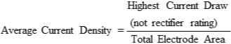
If the average current density is greater than 50 amps per square meter (about 5 amps/ft2), then more Anode area should be added to reduce the current density. Test data has shown that for Anode Cells with Anode current densities greater than 50 amps per square meter (about 5 amps/ft2), the useful life of the Anode (and Membrane Shell) is reduced significantly.
Cell Center-To Center Spacing
The center-to-center distance between TECTRON™ Anode Cells impacts the average electrical resistance of the E-coat system. The greater the center-to-center distance, the greater need there will be to increase voltage. On the other hand, as the Cells get closer and closer together, less voltage is needed. However, at some point the benefit of moving the Cells closer together is lost. Please refer to the table below for more information.
| Cell Size | Minimum | Maximum |
| 1-1/2" | 150 mm (6 in) | 750 mm (29.53 in) |
| 2" | 200 mm (7.87 in) | 950 mm (37.40 in) |
| 3" | 300 mm (11.81 in) | 1425 mm (56.10 in) |
| 5" | 450 mm (17.72 in) | 2250 mm (88.58 in) |
Monorail Conveyor
For tanks with TECTRON Cells on the two long sides of the E-coat tank:
Hoist Conveyor
Cells usually are evenly spaced over the width of the ware package (on each of the long sides of the E-coat tank). In some cases, Cells can be placed on all four sides of the tank, if the aspect ratio (plan view) is close to 1 to 1. Refer to the average center-to-center distance in the table below for recommended Cell spacing. TECTRON™ Anode Cell Selection The effective length of the TECTRON Cell is the exposed height of the ion-exchange membrane below the surface of the E-coat paint. The effective height of TECTRON Cells can range anywhere from less than 0.6 meters to 2.9 meters (24 inches to 114 inches). There are, however, certain standard sizes that represent the more economical sizes of cells to build. Those standard effective heights are 1, 1.4, 1.9, and 2.9 meters. Whenever possible, it is best to select one of the standard sizes and make sure it approximates, or is even a little longer than the work package. To calculate the number of TECTRON Cells required, first multiply the Cell’s effective length by the Anode effective area (see chart below). Then divide the total Anode area by the Anode area of each Cell. Hoist Conveyor – Cells usually are evenly spaced over the width of the ware package (on each of the long sides of the E-coat tank). In some cases, Cells can be placed on all four sides of the tank, if the aspect ratio (plan view) is close to 1 to 1. Refer to the average center-to-center distance in the table below for recommended Cell spacing.
TECTRON™ Anode Cell Selection
The effective length of the TECTRON Cell is the exposed height of the ion-exchange membrane below the surface of the E-coat paint. The effective height of TECTRON Cells can range anywhere from less than 0.6 meters to 2.9 meters (24 inches to 114 inches). There are, however, certain standard sizes that represent the more economical sizes of cells to build. Those standard effective heights are 1, 1.4, 1.9, and 2.9 meters. Whenever possible, it is best to select one of the standard sizes and make sure it approximates, or is even a little longer than the work package. To calculate the number of TECTRON Cells required, first multiply the Cell’s effective length by the Anode effective area (see chart below). Then divide the total Anode area by the Anode area of each Cell.
| Cell Size | Metric | English |
| 1-1/2" | 0.15 sm/m | 0.49 sqft/ft |
| 2" | 0.19 sm/m | 0.62 sqft/ft |
| 3" | 0.279 sm/m | 0.92 sqft/ft |
| 5" | 0.444 sm/m | 1.46 sqft/ft |
BULLETIN 991004