991112 Converting to TECTRON Membrane Electrode Cells
Product Support and Customer Service
For Further support visit our Contact Page
General
The first means of applying E-Coat paint was to use bare electrode plates as the opposing electrode. Later came the Membrane Electrode (ME) System and the introduction of an ion exchange membrane sheet being placed in front of the electrode. In 1985, UFS Corporation brought to market the TECTRON Membrane Electrode Cell – the first patented tubular Membrane Electrode Cell. The TECTRON Cell was second-generation technology and its revolutionary cylindrical design provided many benefits for both end users and electrocoating designers. In 1997, UFSc introduced the TECTRON XL™/SD™ Membrane Electrode Cells with a surface area approximately 25% greater than the original TECTRON Cell. This new and larger TECTRON Cell is the fourth generation technology and it is the latest.
Converting from first generation technology is not difficult and can be seen in pictorial form in Bulletin #xxxxx.
Converting available from UFSc are the Cell Support Frame (PN 187007), Mini Supply Manifold (PN 370045) and Mini Return Manifold (PN 380045), which will allow box cell and C-cell users to easily convert their current E-Coat systems to allow for quick installation of TECTRON Membrane Electrode Cells.
The frame size is determined by the width of the old cell and the gap between each old cell.
EXAMPLE: If the old cell is 1016 mm (40”) wide and there is a 508 mm (20”) gap on either side of each old cell, the length of the Frame would be 1524 mm (60”).
After the old cells have been removed and the new TECTRON Cells have been installed, the Cell Support Frame is placed on the rim of the tank and secured. The supply branch is then attached to the Frame and connected to the existing supply manifold. The last step is to place the return branch pointing towards the TECTRON Cell anywhere from 30 to 60 degrees from the vertical direction. This is done to promote the gravity return flow of the electrolyte solution of the cell.
Installation Sequence
Step 1
Removal of the old cells and installation of new TECTRON Cells. Refer to the manual that came with the TECTRON Cells for installation instructions.
Step 2
Install Cell Support Frame
Step 3
Install Mini Supply Manifold
Step4
Install Mini Return Manifold
HOW TO CONVERT TECTRON MEMBRANE ELECTRODE CELLS
Please read all the instructions listed below carefully before unpacking any further or performing any work to familiarize yourself with the project.
Required Tools:
- Welder
- Pliers
- Screwdrivers
- 3 lb. hammer
THE CELL SUPPORT FRAME (See Figure Below)
The Frame is made such that when more are added, they will fit together in an interlocking method. A wood block and 3 lb. Hammer may be used to tap together each interlocking frame. The same frame is used on both sides of the ED tank. The placement of the first Frame on each side of the tank is important, if additional Frames will be attached.
1.	Insert the Cell Support Frame (PN 187007).
2.	After the Frame has been set in place, measure to insure that the spacing is the same on both sides.
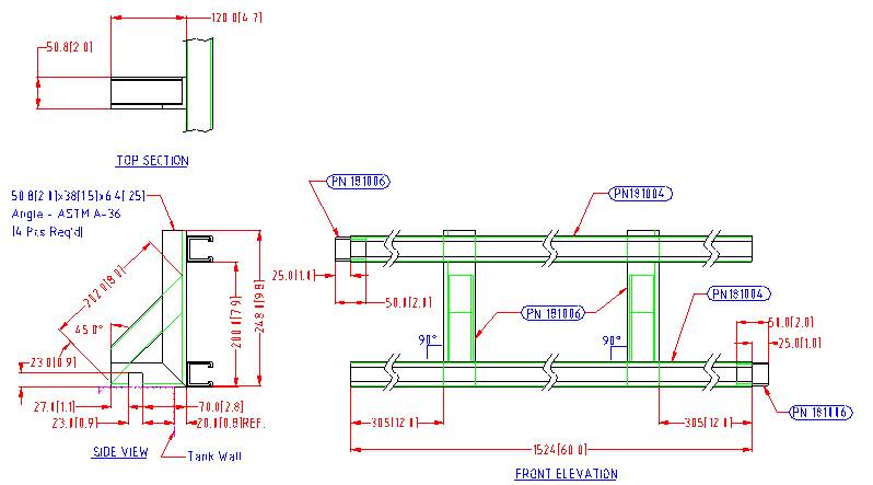
3. Make sure that the notch in the bottom of the angle iron is over the square bar already welded to the rim of the ED tank. Using a welder, secure each angle bracket to the rim of the tank. If necessary, drill holes through the angle brackets and the rim of the ED tank. Use bolts and nuts to secure. NOTE: Be careful to avoid damaging the ED tank lining!
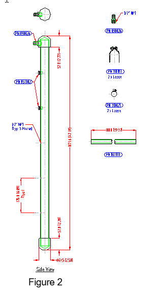
MINI SUPPLY MANIFOLD (See Figure Below)
1.	Set the Supply Branch (PN 370045) on the diagonal strut channels with the hose barb pointing up. TIP: Make sure that the Branch is as high as possible to allow the Return Tubing from the Cell to pass underneath the Supply Branch.
2.	Use two clamps to secure the Supply Branch.
3.	Use one loose ½” NPT x ½” Hose Barb Adapter in the existing manifold. Slip a worm clamp over the length of braided tubing and push the tubing over the Hose Barb Adapter. To secure, tighten the clamp. Repeat the process for the Supply Branch. NOTE:  Usually the Hose Barb is already installed in the branch.
4.	Install the Flow Indicator/Valve. If more than four TECTRON Cells will be used to replace the old cell, remove one of the plugs from the Supply Branch and install another Flow Indicator/Valve.
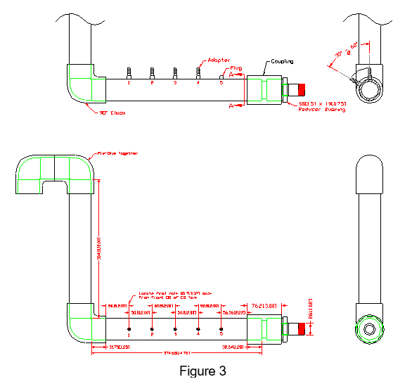
MINI RETURN MANIFOLD (See Figure Below)
The Return Branch (PN 380045) is supplied mostly in loose form, since it has to be used on both sides of the ED tank. The connection point is a NPT nipple. Generally, there is a threaded elbow at the rim of the ED tank into which the Return Branch can be connected.
1.	Locate the match marks on the loose parts.
2.	Thread the nipple/coupler into the existing elbow.
3.	Use PVC primer and glue to attach the piece with the pre-assembled Hose Barbs. NOTE:  Position the Hose Barb leaning towards where the TECTRON Cell will be located.
4.	Glue the elbow on, then the vertical section of pipe, and then the goose neck vent.
5.	Install a shim near the elbow to support the return Branch and insure that there is a 1-2% slope down.
Tubular vs. Box and Crescent-Shaped Cell Comparison
| Tubular Tectron | Box Cells | Crescent Shape C Cells | |
| ELECTRODE | |||
| Material | 316L, 2" Sch 10 (or more) pipe. Other more inert materials available. All steel tested against premature dissolution. | 316 plate 10 gauge or more. | 316 plate 10 gauge or more bent in five places. |
| Weight | 4-13 kg. (9-29 lbs.) | 57-77 kg (125-170 lbs.) | 17-34 kg. (38-74 lbs.) |
| Inspection | Pull from top by one person, 15 seconds. | Remove box from tank. Crane is needed. | Pull out from top. Crane may be needed. |
| ANOLYTE | |||
| Anolyte Flow | Uniform. Optimal flow completely around Electrode; no dead spots. | Uneven. Poor circulation in the corners, where bacteria can thrive and corrosion can occur. | Uneven. Poor circulation in the corners, where bacteria can thrive and corrosion can occur. |
| Individual Anolyte Flow Indicators | Yes | Yes | Yes |
| MEMBRANE | |||
| Type | PTANTM Proprietary Membrane verified with QA. Low water permeability. Other membranes available. | Common variety. Chance of uneven characteristics. | Common variety. Chance of uneven characteristics. |
| Membrane Area vs. Electrode Area | 1.37:1 | 1:1 | 1.06:1 |
| Replacement | Can replace shell. Also can repair small tears and cuts in existing membrane shell. | Yes | Yes |
| HOUSING | |||
| Construction | One piece PVC and PP, therefore no joints or holes that can leak. | Made from stock bar and sheet PVC with gasket and as many as 50 bolts. | FRP with a gasket and up to 40 bolts. |
| Weight | 2-5 kg. (4-11 lbs.) | Up to 68 kg. (150 lbs.). | Up to 23 kg. (50 lbs.). |
| MISCELLANEOUS | |||
| Membrane Guard | Guard effective against membrane cuts. Guard design does not blind membrane. | Heavy grill the "blinds" membrane. | 1: x 1" openings. Size is large enough to expose membrane to cuts from falling parts and maintenance removal tools and to trap paint solids or encourage solids to settle. |
| Number of Connections | More | Few | Relatively Few |
| Location Flexibilty | Can move Cells as needed during installation to avoid obstructions. | Must know locations before ED tank is designed. | Should know locations before ED tank is designed. |
| Dirt Creation | Paint solids flow completely around the Cell. No dirt created. | Paint solids settle out on horizontal surfaces of box causing dirt. | Paint solids fall out of solution in hollow area behind cell causing dirt. |
| Fault Tolerance | If one is shut down, there is minimal loss of anode area and minimal stress on surrounding Cells. | If one is shut down there is significant loss of current flow, affecting paint finish quality and stressing surrounding cells. | If one is shut down there is significant loss of current flow, affecting paint finish quality and stressing surrounding cell. |
BULLETIN 991112