700075
Product Support and Customer Service
For Further support visit our Contact Page
Safety
Think and act in a safe manner. Always disconnect power and use a lockout before you work on the E-coat system, or any of the related subsystems. Observe any confined space conditions. Use the appropriate safety equipment and clothing for the task. Please carefully read all the instructions listed below to familiarize yourself with the project before attempting to perform any of the work.
Required Materials
- PVC Glue & PVC Primer
- 2” PVC Van Stone flange(s)
- 2” PVC EPDM Gasket Flange
- Heavy duty flexible rubber coating
Required Tools
- Gloves
- Pliers
- Hack Saw
General
For safety reasons, make sure that the DC Power Source has been properly disconnected using prescribed Lock Out/Tag Out procedures before attempting to do any work in or around the electrocoating tank. Refer to PVC glue & primer containers for proper application technique. This installation reference is designed to give some guidance in installing replacement membrane shells and electrodes supplied by UFSc for special Floor Electrode part number 700075.
Step 1
Remove old Membrane Shell (PN 710047) from floor of tank and remove Electrode from Shell.
Step 2
Inspect old Electrodes for visual signs of corrosion wear to determine whether or not to replace anode. Please refer to UFSc Service Reference 990129 Stainless Steel Electrode Weight Sampling Program for more instruction on determining Electrode wear.
Step 3
Place electrical cable connection onto Tab of Electrode. Because anolyte will dissolve copper wire, it is necessary to coat these exposed copper connections with a heavy duty flexible rubber coating (silicone free) to keep the anolyte away from the exposed copper. Pull wire through Neck (shipped loose) and local piping (supplied by customer) running up the side of the tank. Also run Supply Tubing through piping and ensure there is enough length to reach Flow Indicators on supply header.
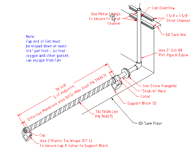
Step 4
(See Figure 1) Place Cell on floor supports to determine the proper length to cut the (shipped loose) Neck to length.
Step 5
Cut the Neck to size and securely glue the Neck into the Collar. Glue the Neck protruding from the Shell into the 2” S80 Van Stone flange (supplied by customer) and glue into the elbow the run of PVC piping that runs vertically up the side of the tank.
Step 6
Secure the flanges together ensuring that the EPDM gasket is intact. Tighten bolts to 25 ft. lbs.
Step 7
Use metal clamps to secure the vertical pipe to strut channels.
Step 8
Use 2 plastic tie wraps to secure Cap & Collar to support block as shown in Figure1.
BULLETIN 993147