UF Housing Assembly
Product Support and Customer Service
For Further support visit our Contact Page
General
Please read all the instructions listed below carefully to familiarize yourself with the project before attempting to perform any of the work or unpacking any further.
Required Materials
- Clean rags
- Glycerin and/or hand soap + water
- PVC Primer & Glue (if applicable)
Required Tools
- Pipe wrench
- Gloves
This document is meant to be used as a guideline for installing UF Housing for spiral wound membrane UF (ultrafiltration) Elements. A UF Module is defined as an UF Element installed in an UF Housing. There are two general types of UF Housing designs: one with threaded paint connections and the other with PVC slip fit paint connections. 1. Generally the ED paint enters through the bottom side of the UF Module and paint exits though the top connection. The connection size is generally 1-1/2” NPT, 1-1/2 PVC Slip for 8” and 6” UF Housings and could be smaller for other sizes.
2. Line up and confirm all the parts to make the connection from the lower ED paint manifold of the UF Rack. Usually the connection will be made through a true union valve some type of sanitary quick connect. If your UF Housing has NPT threaded paint connections, then skip to #5.
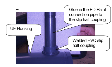
3. If your paint connections are PVC slip, then you will have to glue in the appropriate PVC pipe to connect to the ED paint manifold. Refer to your standard practice manual for method to make solvent weld PVC joints, or see Service Reference #993116 for more information.
4. Glue the appropriate end of the pipe into the slip fitting of the PVC half coupling that is PVC welded to the large diameter PVC pipe that forms the exterior of the UF Housing. Repeat for the other ED paint connection. See the photo below.
5. The Housing must be supported either at the bottom of the Housing or by using 2 appropriate sized conduit (i.e. pipe) clamps around the Housing near its center on 12” center to center.
6. Install the bottom Victaulic fitting on the UF Housing.
7. Rest the UF Housing on its support or else secure it with 2 clamps.
8. Complete the lower connection to the ED paint manifold, but do not too tight yet.
9. Make the connection on the upper end of the UF Housing to the other ED paint manifold and make sure the connection is snug. Take a look at both the upper and lower ED paint connections to the ED paint manifolds. Make sure that all piping is straight and true. If the centers of the manifolds are plumb, then if you place a level on the UF Housing it should be plumb as well. Adjust as required. 10. Tighten the upper and lower ED paint connections.
11. You are now ready to install the UF Element.
12. Afterwards the Top Cap of the UF Housing is ready to be installed and secure it with the other Victaulic clamp.
13. Make the appropriate connection on the Top Cap to the permeate discharge piping.
14. At this point follow your normal startup procedures for a new UF Element.
For more information See the original manual that came with the equipment or call UFS.