Diode Heat Sink One+ C Cell
Product Support and Customer Service
For Further support visit our Contact Page
Safety
Think and act in a safe manner. Always disconnect power and use a lockout before you work on the E-coat system, or any of the related subsystems. Observe any confined space conditions. Use the appropriate safety equipment and clothing for the task. Please carefully read all the instructions listed below to familiarize yourself with the project before attempting to perform any of the work.
Required Materials
Required Tools
General
Please read all the instructions listed below to familiarize yourself with the project before attempting to perform any of the work. These instructions are appropriate for either the P4 or P5 Version of the One+ C Cell. Required tools: drill, 3/16” drill bit, heat gun, Phillip screw driver and crescent wrench .
Step 1
Make sure power has been shut off and locked out before working on One+ C-Cells.
Step 2
Before starting. it is important that the One+ PVC brackets and spacers are attached properly! See below.
Step 3
Attach heat sink assembly to PVC plate with four 1/4-20 x 1-1/4 hardware sets included in the shipment (holes are already pre-drilled in PVC plate).

Step 4
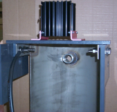
Place assembly on the top of One+ C Cell brackets. Move it as far back as possible.
Step 5
Leave about 10mm of overlap on each side of One+ C Cell brackets. See below.

Step 6
Drill 1/4” holes in corners of the PVC plate & and 3/16” holes (about 1-1/4” deep) into the Brackets. These holes must be drilled straight & through the center of the Brackets.
Step 7
Secure the PVC plate with four 1/4” self tapping x 1-1/2” screws each.
Step 8
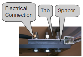
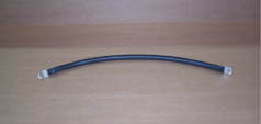
Connect 1/2” lug end of cable lead to the inside surface of the Tab of the One+ C Cell. See picture #1. Slip a piece of shrink wrap over the pigtail of the diode.
Step 9
Connect the 1/4” lug end of cable lead to the diode installed to the heat sink. Use 1/4” hardware included in the shipment. Set the shrink wrap with a heat gun and tape the bolted joint to isolate it.
Step 10
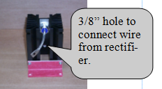
Connect wire from rectifier/anode bus bar to the 3/8” hole in the heat sink with the hardware included in the shipment.
BULLETIN 993419