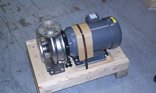
CIP Pump / Motor PN 200092
Product Support and Customer Service
For Further support visit our Contact Page
Safety
Think and act in a safe manner. Always disconnect power and use a lockout before you work on the E-coat system, or any of the related subsystems. Observe any confined space conditions. Use the appropriate safety equipment and clothing for the task. Please carefully read all the instructions listed below to familiarize yourself with the project before attempting to perform any of the work.
Required Materials
- Replacement pump, PN 200092
- Return Authorization # (if the pump is to be returned for service)
Required Tools
- Open Wrenches:3/4”
- Socket drive and ¾” socket
- Torque wrench with same drive as ¾” socket: 12 & 24 ft-lbs usage
- Flat blade screw driver
- Large slip joint pliers
Step 1
Turn off Power to the CIP Panel and place a lockout/tagout card on the power source as required by your safety program.
Step 2
Close V7 & V8 valves to isolate the CIP.
Step 3
Use a ¾” open end wrench & ¾” socket wrench to loosen the bolts on the suction side of the pump. Set aside the hardware & flange gasket. Those bolts are slightly longer than the ones for the discharge flange.
Step 4
Use a ¾” open end wrench & ¾” socket wrench to loosen the bolts on the discharge side of the pump. Set aside the hardware & flange gasket.
Step 5
Use a ¾” open end wrench to loosen the 4 bolts that secure the pump base to the strut channel.
Step 6
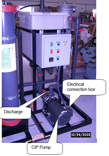
Use a flat blade screw driver to open the electrical box on the side of the motor and disconnect L1, L2, L3, and the ground coming from the Control Panel.
Step 7
Disconnect the electrical conduit fitting from the motor electrical connection box with the large slip joint pliers.
Step 8
Remove the old pump and set aside.
Step 9
Remove the new pump from its shipping container. Remove steel band and take new pump off the base. Place old pump in its place, use steel band and replace top of box and re band this too and send pump back to UFS.
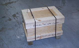
Step 10
Place the old pump into the shipping container, secure with a new steel bands and return the pump to UFS if so instructed.
Step 11
Secure the pump base to the strut channel with the ¾” open end wrench. Make sure the suction flange mates up with the PVC flange – adjust as required to get the flanges to mate and make sure the suction gasket is in place first.
Step 12
Use ¾” open wrench & ¾” socket in the torque wrench. Use the longer hardware & EPDM flange gasket to attach the 2” PVC flange to the suction of the pump. Tighten (25 ft-lbs Max) the bolts on the suction side of the pump in a alternate tightening from side to side to make sure the flange is properly tightened together.
Step 13
Repeat Step 12 for the discharge, except the Use the shorter hardware and only 12 Ft-lbs of torque.
Step 14
Open the electrical connection box on the side of the motor and connect the electrical conduit fitting to the motor electrical connection box.
Step 15
Connect L1, L2, L3, and the ground wires as required. Make sure the leads are grouped together as required for the voltage used to operate the motor.
Step 16
Close the electrical connection box.
Step 17
Open V8 and properly prime the new pump with DI water before the pump is operated, otherwise the pump may be damaged.
Step 18
Remove the lockout/tagout from the power source and turn power back on to the CIP Control Panel.
Step 19
Bump the motor for 1 – 2 seconds and observe the rotation of the fan. Looking at the fan the direction of rotation needs to be clockwise. If the fan turned the other direction then change the lead wiring to the pump and re bump motor again.
Step 20
The pump is now ready for service.
Step 21
Return the original pump is so requested.
Reference
BULLETIN 99