T1 & T2 Flow Indicators
Product Support and Customer Service
For Further support visit our Contact Page
Safety
Think and act in a safe manner. Always disconnect power and use a lockout before you work on the E-coat system, or any of the related subsystems. Observe any confined space conditions. Use the appropriate safety equipment and clothing for the task. Please carefully read all the instructions listed below to familiarize yourself with the project before attempting to perform any of the work.
Required Materials
- Teflon Pipe Thread Tape
Required Tools
- 17 mm (11/16”) Open End Wrench
General
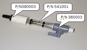
UFSc Flow Indicators are designed to indicate and regulate flow to the TECTRON™ Membrane Electrode (ME) Cell. In some instances the Flow Indicator will become damaged, broken or covered with paint and it may be necessary to replace one or more parts.
Replace PN 36003
Step 1
Hold assembly P/N 225010 (Flow Indicator) such that the old P/N 360003 is pointing up and unscrew. NOTE: Take care not to loose P/N 541001/541002.
Step 2
If the new P/N 360003 does not have Teflon tape on the threads, then place tape on both ends. Turn the handle on P/N 360003 so that it will close.
Step 3
Thread P/N 360003 (end pointing in same direction as the valve handle) into Flow Indicator body. Hand—Tighten ONLY. Do not use any tools to tighten.
Replace PN 541001 / 541002
Step 1
Follow Step #1 from above.
Step 2
Remove the old P/N 541001/541002 and place the new part into the Flow Indicator body.
Step 3
Follow Step #3 from above. =Replace PN 090003 / 090008
Step 1
Use the wrench to unscrew the old P/N 090003/090008.
Step 2
If the new P/N 090003/090008 does not have Teflon tape, then place tape on the part.
Step 3
Use the wrench to thread in the new P/N 090003/090008.
Installation
Step 1
Thread the repaired valve on to the electrolyte supply manifold and confirm that the valve handle operates normally.
Step 2
Turn on the electrolyte pump and look for leaks in the assembly.
Reference
BULLETIN 993109
