Cell Support Frame PVC Supply and Return Branches
Product Support and Customer Service
For Further support visit our Contact Page
Safety
Think and act in a safe manner. Always disconnect power and use a lockout before you work on the E-coat system, or any of the related subsystems. Observe any confined space conditions. Use the appropriate safety equipment and clothing for the task. Please carefully read all the instructions listed below to familiarize yourself with the project before attempting to perform any of the work.
Required Materials
- 1-1/2” Metal 2 Piece Clamp (UFSc P/N 310011)
- Wood Block
Required Tools
- Welder, Pliers, Screwdriver, 3 lb Hammer
General
The Cell Support Frame and its accompanying Electrolyte Supply and Return Branches (mini manifolds) allow for the quick installation of TECTRON™ Membrane Electrode (ME) Cells in place of box or crescent-shaped cells. The frame size is determined by width of old ME Cell and gap between ME Cell (i.e. - If your old ME Cell is 1016 mm (40”) wide and there is a 508 mm (20”) gap on either side of each old ME Cell, then the length of the Frame will be 1524 mm (60”))
After the old ME Cell is removed, the Cell Support Frame is placed on the rim of the tank and secured. Next, the Supply branch is attached to the Frame and connected to the existing supply manifold. Finally, the Return Branch should point towards the TECTRON ME Cell anywhere from 30 to 60 degrees from the vertical direction. This is done to promote the gravity return flow of electrolyte solution of the ME Cell.
=Frame PN 185007
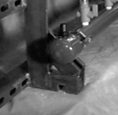
Step 1
After the old ME Cell is removed, insert the Cell Frame (P/N 187007). The Frame is made such that when more of them are added, they will fit together in an interlocking method (a wood block and 3 lb hammer may have to be used on the sides to tap together each interlocking Frame). The same Frame is used on both side of the ED tank. The placement of the first Frame (on each side) is important because all the others will have to be attached. After the Frame has been set in place use a tape measure to insure that there is the same spacing on either side of it.
Step 2
Insure that the notch in the bottom of the angle iron is over the square bar already welded to the rim of the ED tank. Use a welder to secure each of the angle brackets to the rim of the tank. Do not damage the ED tank lining. If necessary, drill holes through the angle brackets and the rim of the ED tank using nuts and bolts to secure.
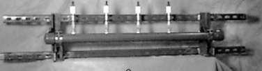
Mini Supply Manifold PN 370045
Step 1
Set the Supply Branch (P/N 370045) on the diagonal strut channels with the Hose Barb pointing up. The branch needs to be as high as possible, so the Return Tubing from the ME Cell can pass underneath the Supply Branch. Use two clamps to secure the Supply Branch.
Step 2
Use one of the loose 1/2” NPT x 1/2” Hose Barb Adapters in the existing supply manifold. Slip over a worm clamp a length of braided tubing and push the tubing over the Hose Barb Adapter. Secure by tightening the clamp. Repeat the process for the Supply Branch. (Usually the Hose Barb is already installed in the branch)
Step 3
Now you can install the Flow Indicator Valve (P/N 225 series). If there will be more than four TECTRON ME Cells used to replace the old ME Cell, then remove one of the plugs from the Supply Branch and install another
Step 4
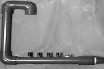
The Return Branch is provided mostly in loose form because it has to be used on both side of the ED tank. The connection point is a NPT nipple. Generally there is a threaded elbow (at the rim of the ED tank) into which the Return Branch can be connected.
Step 5
There are match marks on the loose parts. Thread the nipple/coupler into the existing elbow.
Step 6
Use PVC primer and glue to attach the portion with the pre-assembled Hose Barbs. Take note to position the Hose Barbs leaning towards where the TECTRON ME Cell will be located.
Step 7
Glue the elbow on next, followed by the vertical section of pipe and then the goose neck vent.
Step 8
Install a shim near the elbow to support the Return Branch and insure that there is a 1 - 2% slope down.
BULLETIN 993118